Bore length, also known in the industry as sleeve length, is often overlooked in favor of maximum cubic inches, but in order to build a long-lasting, high-powered engine it is a major consideration. We explore sleeve length, stroke, and selecting rotating assembly components that work in harmony.
An engine is an ecosystem of moving, complimentary parts. Changing just one of those parts affects the entire system as a whole. Stroker crankshafts, while the premier way to add power, torque, and displacement, can dramatically change the operating condition of the piston. Without careful attention to detail and proper planning, sometimes for the worse. In this segment, we show you how to ensure your stroker crank works well with the piston and rod combination at hand.
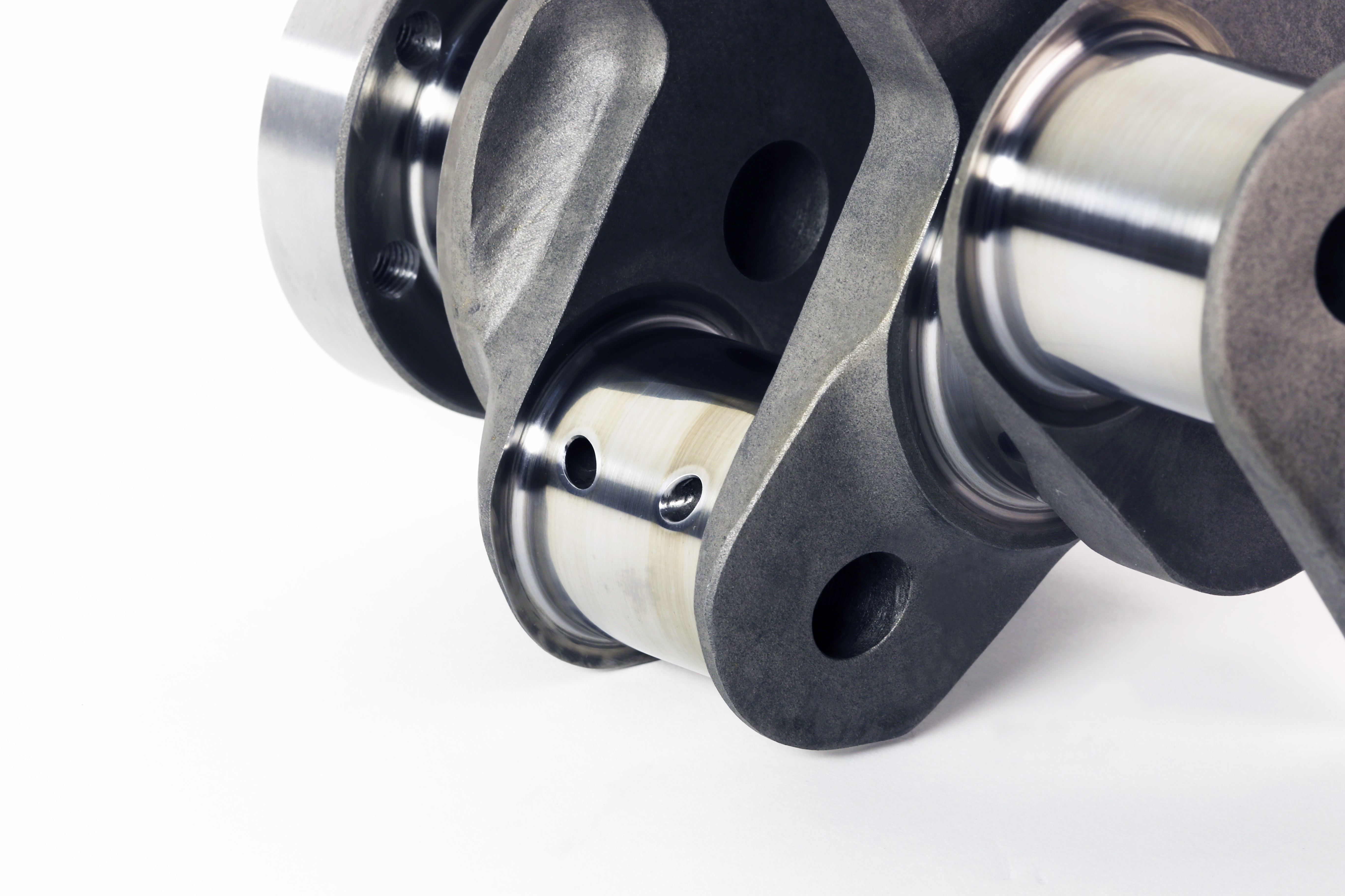
First, it is important to consider the length of the cylinder (which is often referred to as the sleeve). Many builders spec a longer stroke engine that pulls the bottom of the piston partially out of the bore at BDC (bottom dead center). There are ways to make this work, but when the piston’s gauge point is uncovered the piston rocks too far and the skirts are instantly damaged. To counter this, you must spec a combination of rod length, ½ the stroke length, and sleeve length that ensures the piston’s gauge point will remain properly captured throughout BDC.
In the short video above, notice how the engine on the left pulls the piston out of the cylinder slightly at bottom dead center. This can cause a host of problems including oil consumption and increased wear of the piston skirts.
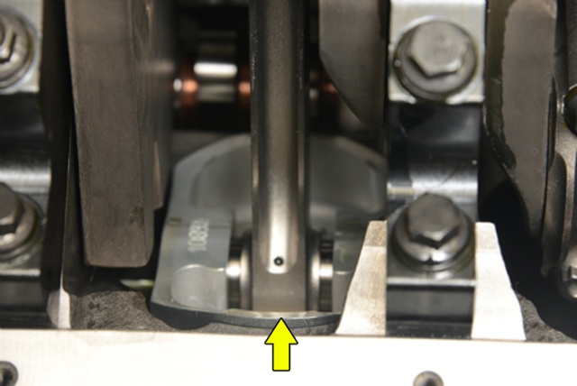
Before you spec a stroker combination you must measure the existing sleeve length and determine if it will fit properly. You must calculate ½ the stroke length, rod, and gauge point to see if it will accommodate your needs. To ensure safe operation the gauge point must be at least 0.250 or more above the bottom of the sleeve so it will completely capture the piston and prevent rocking. The gauge point can vary significantly depending on the forging style so you will need to know which piston you plan to run in order to accurately calculate your dimensional stack.
You can model this on paper using the following dimensions:
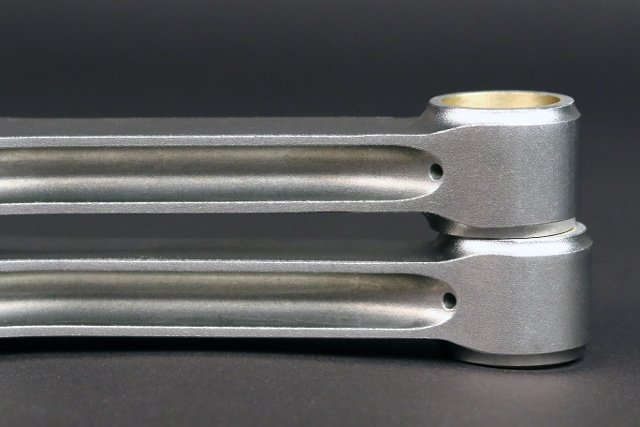
Rod Length
½ Stroke Length
Gauge Point Dimension
The total of all these must be less than the length of your sleeve by 0.250-inch safety margin.
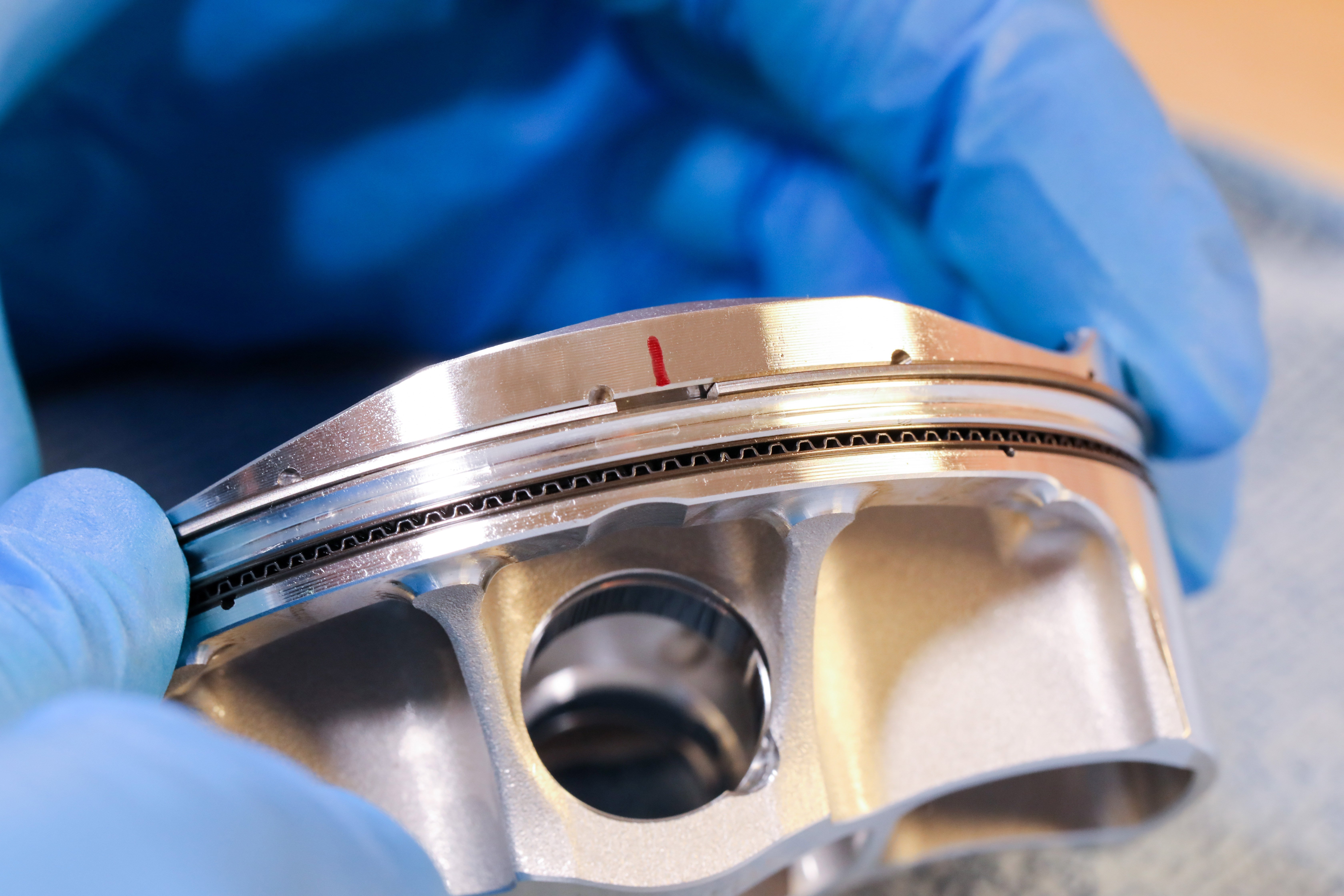
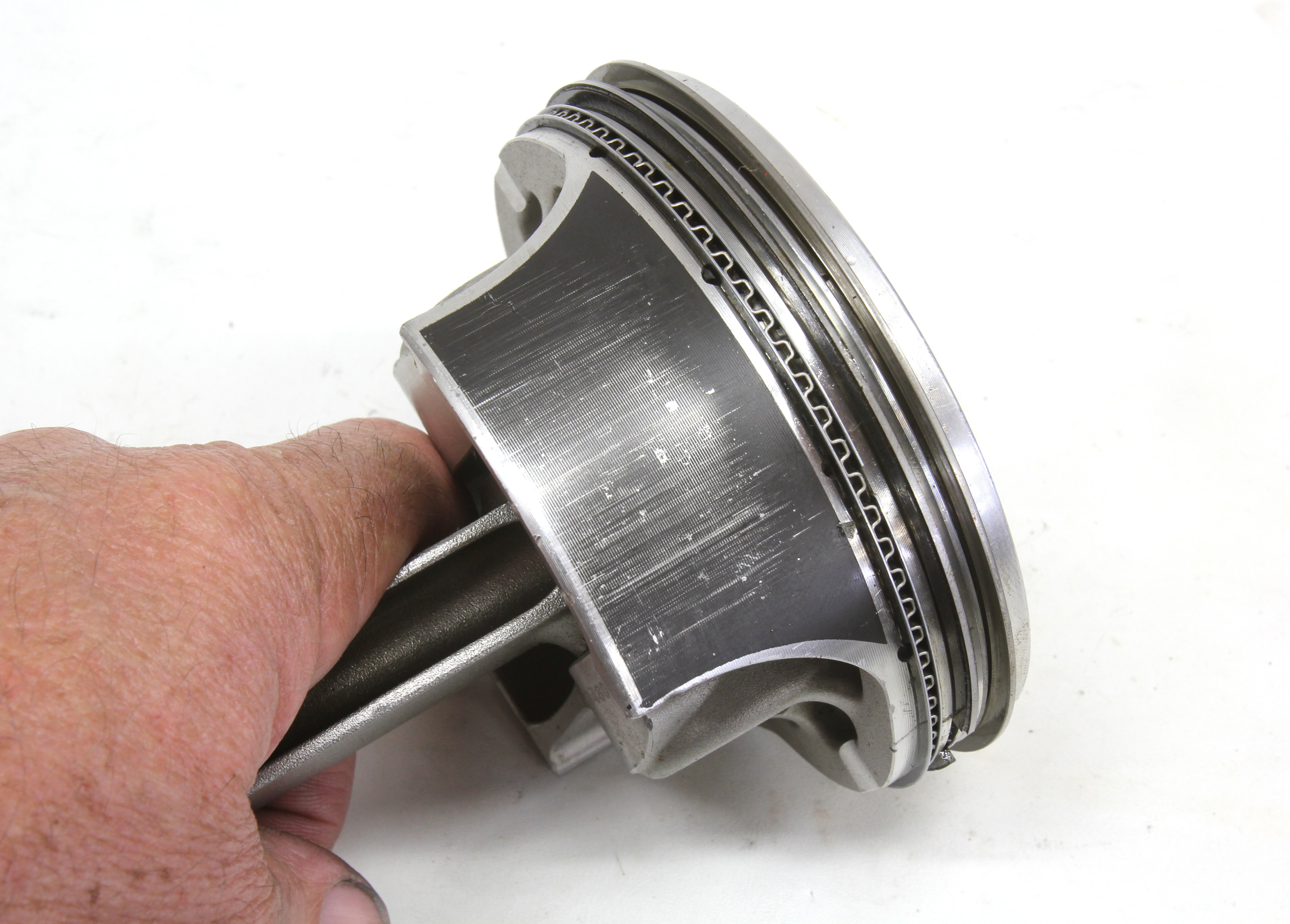
The location of the gauge point is the critical part because that is where the piston will rock if it moves lower than the bottom of the sleeve. The gauge point (CH or checking height) is the lower stability point on the piston skirt. It works in conjunction with the rink pack to keep the piston square in the bore. If the piston rocks, the skirts dig into the sleeve and are instantly ruined. If you cannot achieve the proper dimensional stack, you will not be able to stroke the engine to your desired spec.
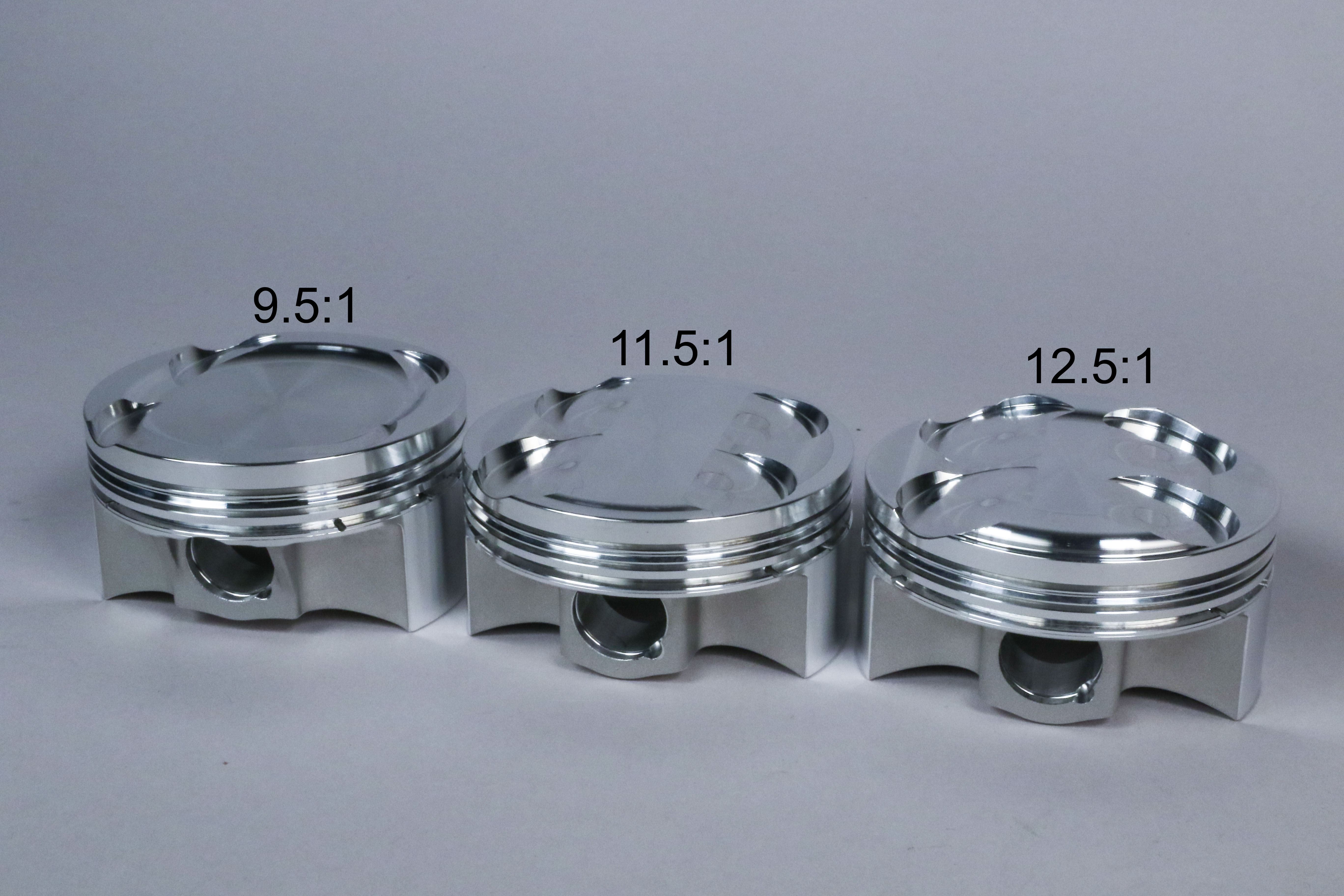
According to Alan Stevenson, at JE Pistons, “Our standard for total piston height is CH +1.00”. The gauge point varies by forging design: full round forgings have different cam shapes than slipper-style (what we call FSR or Forged Side Relief) forgings. Typical gauge point for a full round is .500” above the bottom of the skirt and .275” up from the bottom on an FSR.”
The formula for determining if the gauge point is captured on a full round piston is:
Sleeve length – (CH + .750”) – stroke.
The .750” number is an “aim to” that is arrived at this way: Overall length is CH + 1”, and the gauge point is .500” above the bottom of the skirt, so it is expressed as CH + .500” + .250” (the safety margin) or CH + .750”.
So, if we look at a typical 383 SBC (3.750” stroke, 6” rod, 1.125” CH) that has, say, 5.7” long sleeves:
5.700 – (1.125 + .750) – 3.750 = 0.075”. This means we’re .075” to the good. Any positive number using this formula means the gauge point will be captured, plus have .250” safety margin below the gauge point, plus the difference of the formula. In this case the gauge point would be captured by .250” + .075” = .325”.
For an FSR-style forging, the .750” number changes to 0.975” since the gauge point is only .275” above the bottom of the skirt and we still need the gauge point captured by .250”. So with the same example engine:
5.700 – (1.125 + .975) - 3.750 = -.150. This means we’re .150” short of the .250” safety margin, or conversely that the gauge point is only captured by .100”.
Stevenson added, “This is also where the type of cam shape on the skirts goes from important to critical. Certain cam shapes taper outward below the gauge point, others go straight down from the gauge point, while others have “tuck” underneath the gauge point. If part of the skirt protrudes at BDC, the first two will wear very visibly and very quickly while the third will handle the protrusion with much less drama.”
“We recommend beginning with these basic calculations and then having a conversation with your piston manufacturer to decide on the right cam shape based on the severity of the protrusion.”
Measuring your sleeve length, and calculating how it will accommodate your stroker application is mission critical. A piston that drops too far out of the bore near the gauge point amounts to moving parts hitting each other in a running engine and that is never a good thing.