Finite Element Analysis is a way to analyze the stress of a part through computer modeling so they can be designed as accurately as possible. Inside we explain the technology.
You hear it all the time – change is good. Some of that change has to do with learning what’s new. As the technology of high performance and racing increases in complexity, this also introduces new terms that may not be familiar. But it doesn’t have to be difficult. Let’s take the case of forged pistons and a design tool called FEA. This doesn’t stand for the Futuristic Engineering of Aid or even French Experimental Aircraft – the acronym stands for Finite Element Analysis. So right here in our first paragraph you’ve already learned something that might lead your car buddies to think you’re pretty sharp.
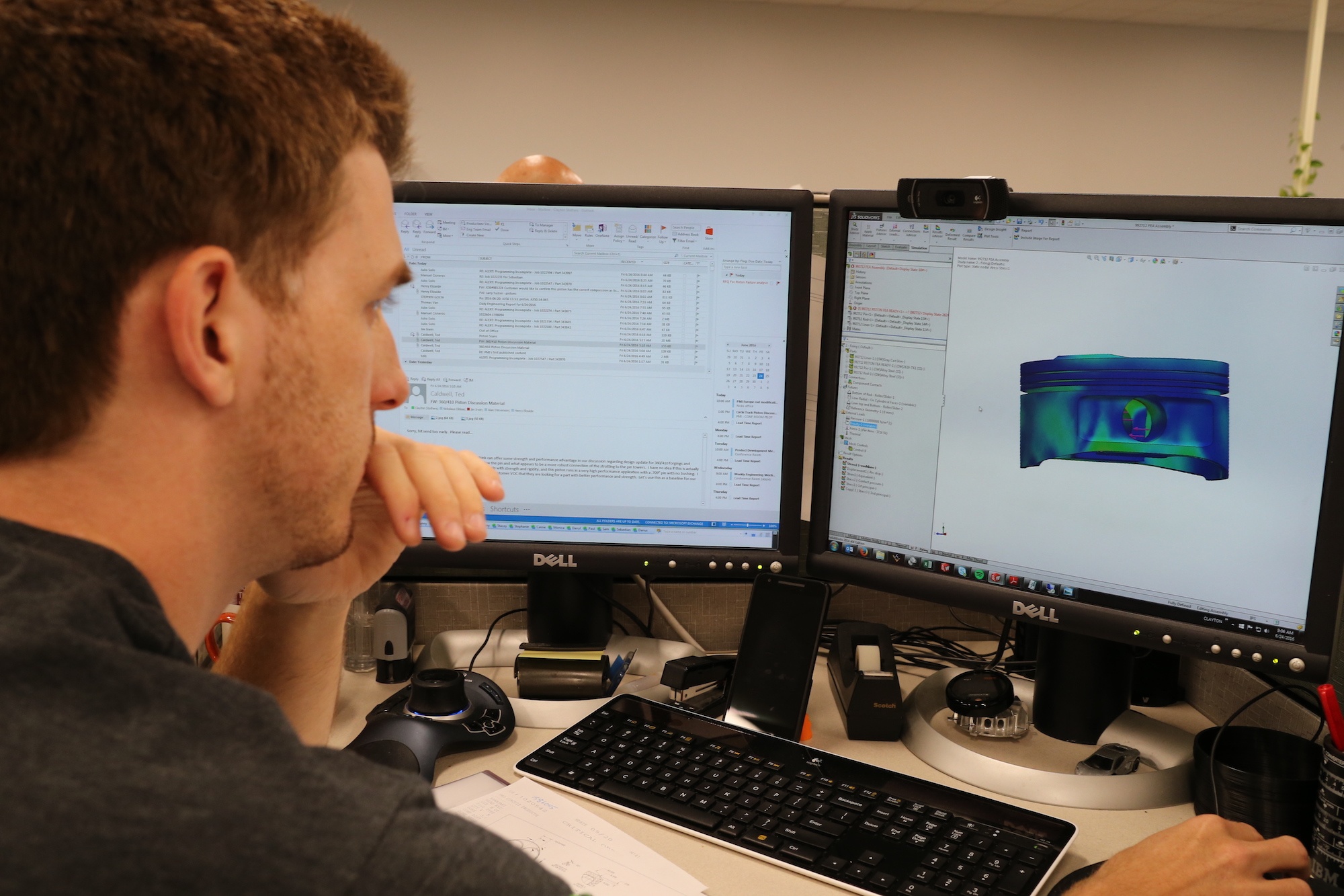
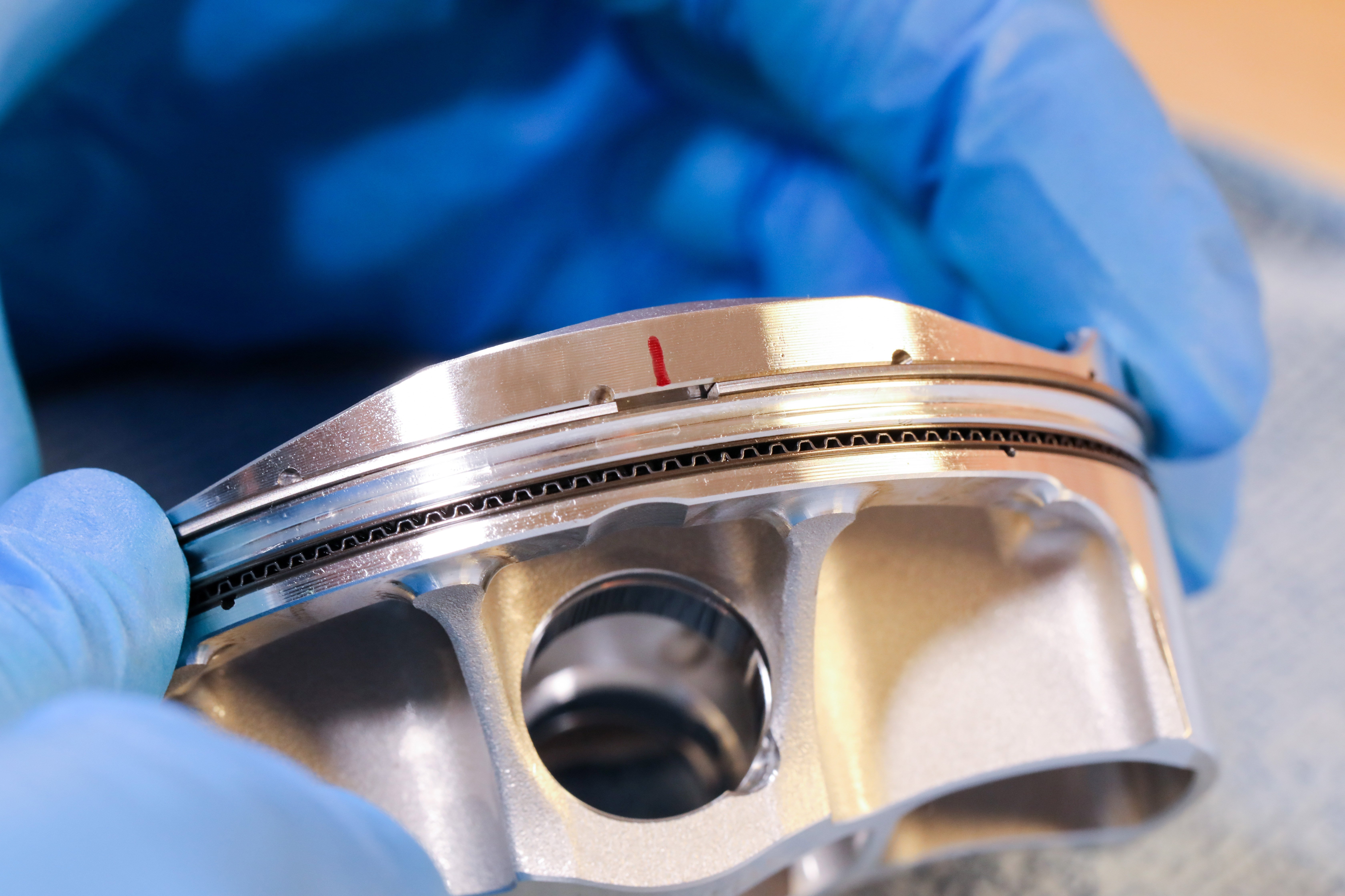
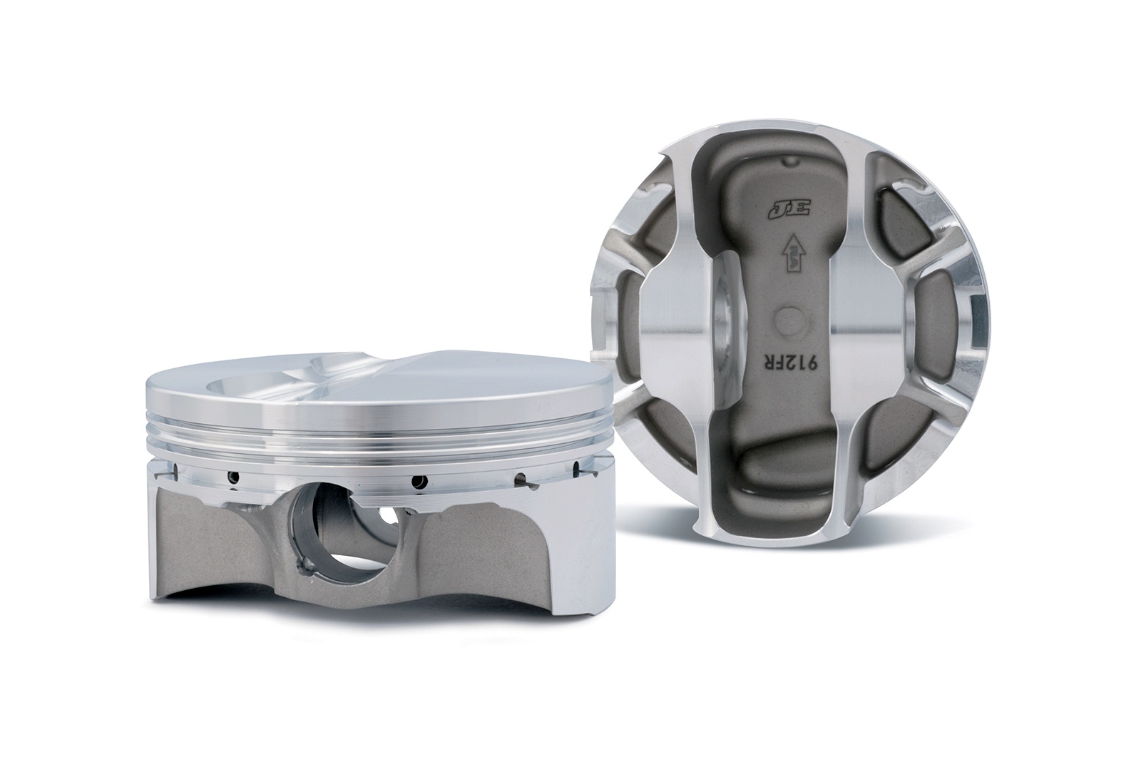
It’s not surprising that all JE pistons begin life on the computer screen. One way to reduce the cost of race or street pistons is to do as much development work as possible on the computer, which leads to a shorter lead time from design to a piston sitting on the shelf.
What is FEA?
So what is FEA and why should we care? If you into high performance engines, then you already know that if your heads offer the airflow to spin that engine faster – you can make more horsepower. But this puts a price on piston durability. That’s where FEA can be an important step toward better pistons.
Finite Element Analysis is essentially a complex computer program that helps the piston designer create a better part. The program can pre-determine a weak point in the design before it ever leaves the confines of the computer design screen.
In the not-so-distant past, a piston designer applied his experience with a sketch on paper that eventually led to a fully-functional forged prototype. This one-off part was then squeezed into an engine and abused on the dyno or in a race car and then removed and carefully evaluated. This process demanded tremendous time and plenty of resources. Today, that evaluation process still occurs but only after the program has created significant feedback in the design stage as to where the stresses in the piston will occur.
To get started, let’s first define what we’re talking about. Finite Element Analysis is a computer program that evaluates how objects are affected by stress. The finite element process applies simulated thermal and mechanical stress to a complex component like a piston and predicts where that stress will appear on the piston. By applying certain techniques, the designer can reshape the piston to reduce or redistribute the stress to make the piston more durable.
When a component is designed on a computer screen, the engineer uses a program called SolidWorks to create thousands of three-dimensional cubes that represent a small portion of the component. Each of these cubes will react in a predictable manner when assigned to represent a given material such as the 2618 aluminum alloy used in JE race pistons. The advantage of the computer program is that it can quickly perform hundreds of thousands of finite calculations that are used to predict how the design will react to stress. The key is to know what stresses to apply and what to look for as a result of those tests.
In Practice
As an example, an internal combustion engine enthusiast might consider that withstanding combustion pressure would be the ultimate concern when designing a piston. While that is certainly important because the loads imposed are considerable, there are other areas involved with a piston’s physical operation that are perhaps of even greater concern. One of the most critical is the piston’s ability to withstand the high g-forces imparted into a piston when it changes direction. A critical point is where the piston stops momentarily at top dead center (TDC) and then the crankshaft, through the connecting rod, yanks downward on the wrist pin.
At high RPM, this simple change in direction places incredible tensile (stretching) loads on the piston’s pin boss area, stresses that, in many cases, are the exact opposite of the compressive loads placed on the piston during the combustion cycle. So the piston engineer is faced with creating a design that is not only lightweight (which reduces the g-force loads), but is also strong and durable enough to sustain these enormous cylinder pressure loads. How much force are we talking about? A typical small-block Chevy with a 400 gram piston at 7,000 RPM could easily be subjected to g-forces of 3,400 g’s – or just shy of 3,000 pounds of force. Think about that. As RPM increases, so does the g-forces because the piston must travel the same distance (the stroke) in a shorter period of time. Of course, if we make the piston lighter or shorten the stroke, the forces will be reduced.
Reducing Mass and Friction
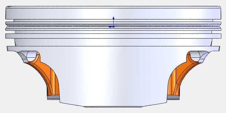
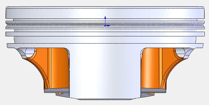
One area where reduced mass improves almost all areas of piston design is JE’s asymmetrical piston skirt technique. All reciprocating internal combustion engines create what is known as thrust loads on a given side of the piston. These are lateral, or side loads imparted through the piston into the cylinder wall based on the direction of rotation and a combination of crankshaft stroke and rod angle, among other factors. On a typical V8 engine that rotates clockwise, the loaded thrust side is the inboard (intake) side of the left bank and the outboard (exhaust) wall of the right bank.
.jpg)
Most pistons are designed with symmetrical skirts for both the major and minor thrust sides of each piston. But during the creation of JE’s forged side relief (FSR) design, enlightenment took a step forward by reducing the skirt area on the non-thrust side of the piston. This reduces the mass while also lowering friction which further diminishes the g-load on the piston. All of this was first created using SolidWorks and then perfected with FEA. That’s what makes this technology so efficient.
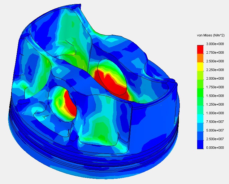
The accompanying photos and illustrations will help make these descriptions a little more clear, but they also demand some explanation. For example, FEA results use a simple color-coded depiction of load concentrations with light green as the least stressed portions and moving toward warmer colors for increased load with red areas reveal the greatest load. Ideally, the designer would prefer that in every test case that the FEA tests would reveal low stress concentrations, but that only happens in science fiction novels. In the real world, high cylinder pressures or extreme engine RPM applications will produce high stress levels that will be indicated in red.
If you look closely, the chart is delineated in a scale called the von Mises scale. Essentially the scale can be set by the engineer to any level he desires. Often, he may want to see the stresses across a tighter scale to get an idea of exactly where the stresses are the greatest and where these can be relieved or at least spread over a larger area to reduce the concentration of the load. You can see that in the FEA analysis of the pressure loading on the piston (Photo 02) that the top of the wrist pin boss area show the highest load concentration. This is to be expected and as long as the stress does not exceed the piston’s capabilities.
.jpg)
The images of both sides of the FSR piston showing the major and minor thrust sides of the piston reveal how even the major thrust side shows acceptable loading in the center of the skirt. Plus, the low thrust side, even with its much smaller contact area, is still well within acceptable levels. This means that even with its smaller contact area, the piston can accommodate this load and be completely durable.
There’s far more to the FEA story than we can jam into this short introduction, but ultimately these computer-aided design advantages allow JE to produce a superior product while still making the pistons affordable. And that’s a great combination.