The LS remains a pushrod, 2-valve V8 in a land of DOHC engines. Its bore centers, the distance between the centerline of each cylinder, has not changed since 1955. Chevrolet considers the LS to be simply an extension - a new branch of the original small-block V8 tree. To this end, Chevrolet announced that sometime during 2011, the 100 millionth small-block trundled down the assembly line. Just ponder that ridiculously large number for a moment and you can appreciate why this engine entertains so much attention. No engine in the history of the automobile comes close.
As a tip-of-the-hat to its small-block legacy, even the LS engine’s bellhousing pattern is the same as its predecessors, with a minor relocation of the upper bolt hole on the passenger side to the 12 o’clock position. This one detail – the continuation of the bellhousing pattern - has probably done more to promote and encourage the proliferation of the LS engine family in the performance industry than any other single step. This seemingly insignificant choice offered an easy path for enthusiasts to adapt the LS to existing transmissions. Sometimes it’s the little things that make a huge difference.
What we will outline here are some of the more important aspects of the Gen III/IV engine family. We will save information on the latest Gen V gasoline direct injection (GDI) family of engines for a separate story, as that engine family continues to evolve. In this story, we will take a hard look at many of the critical details that will make your next foray into the LS engine’s world both easier and less intimidating.
Overview
The LS1 debuted with the C5 Corvette in 1997. This 5.7L (345ci) engine immediately promised great potential if for no other reason than it was the first Chevrolet production all-aluminum small-block V8. Right away this meant improved performance just from the reduction of roughly 50 pounds of dead weight compared to the iron block Gen I small-block. The difference between the iron and aluminum LS block is even more surprising with the production LS1/LS2 weighing 110 pounds less than a 6.0L iron truck block.
The LS series of engines requires no distributor. Instead the ignition is controlled by the ECU, firing a set of eight coils mounted near the spark plugs. The LS family also utilizes a different firing order: 1-8-7-2-6-5-4-3. But these were just the first few steps in this engine’s evolution.
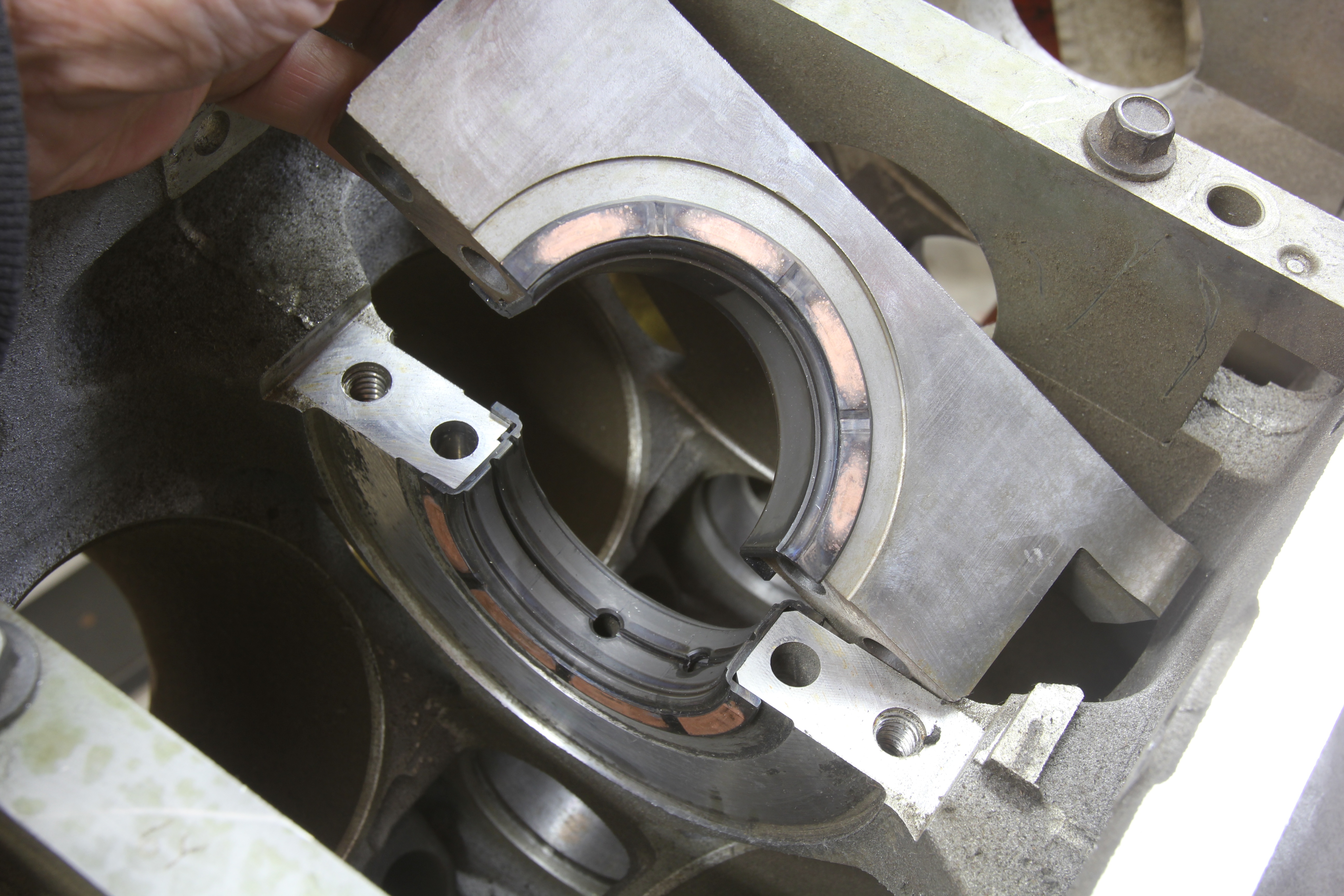
The LS was originally intended and designed as an alloy block. To add strength, engineers created a deep skirt block where the pan rail extends below the bottom of the 4-bolt main caps using a pair of 8mm horizontal bolts to laterally locate each main cap. Other major changes included a larger 55mm (2.165-inch) journal hydraulic roller camshaft and unique, cathedral-shaped intake port heads. Topping off the engine is a thermoplastic composite intake manifold intended to reduce weight and lower inlet air temperature.
A multitude of variants of the original LS1 have been produced. While all the attention is paid to the high performance engines with their big power numbers, the majority of LS engines are actually aimed at truck and heavy-duty applications, equipped until just recently with iron blocks and (with one exception) aluminum heads. The Gen III and later Gen IV truck and small SUV engines expanded the displacement curve from 4.8L (293ci), to 5.3L (325ci) and 6.0L (364ci) versions. If this lineup sounds a little bit like a 21st century remake of the venerable 283, 327 and perhaps the 400ci predecessors, you would be correct.
The 3.89-inch bore LS1 was quickly followed by the LS6, offering more cam timing and compression. The next step was to increase displacement with the LS2 in 2005 by bumping the bore to 4.00-inches that duplicated the bore and stroke of the 6.0L truck engines in an all-aluminum configuration, still with cathedral port heads.
A move to the LS2 Gen IV configuration meant several changes including electronic throttle control (ETC). This was followed soon by the larger displacement LS3 at 6.2L that started a seismic shift in LS engine building with the debut of the rectangle port cylinder heads. Previous LS engines had all employed cathedral port heads. Many enthusiasts misinterpreted the move to the large intake ports as a quest for increased airflow. But engineers were actually more interested in minimizing pumping losses at part throttle by manipulating the throttle to reduce light throttle engine vacuum in an attempt to improve fuel mileage.
The biggest displacement leap occurred with the LS7 7.0L (427ci) engine for the 2006 Corvette. This became the largest displacement LS family engine in the production lineup with a 4.125-inch bore and a 4.00-inch stroke. The longer stroke necessitated an increase in the cylinder bore length in order to safely accommodate the additional piston travel through bottom dead center (BDC). This highlights perhaps one of the LS engine’s weak points in that the standard length of the cylinder sleeve in this entire family of engines (except for the LS7) is somewhat short. This requires attention to detail when adding a longer crank beyond 4.100-inches in length.
While the 427 remains the largest engine, Chevrolet did more than just increase the size of its base engines from the 6.0L LS2 to an even larger 6.2L LS3 Gen IV engine. These Gen IV engines also incorporated several major changes that constitute the Gen IV designation. The major change was a switch to a 58x (60 teeth minus 2) reluctor wheel on the crankshaft. Gen III engines used a 24x wheel, so the larger tooth count improved resolution to accompany the upgrade to the more powerful E38 ECU. This was in anticipation of even more sophisticated engine controls that soon appeared with the emergence of what GM calls Variable Valve Timing (VVT), first introduced with the 2007 Cadillac Escalade and several other SUV’s.
Many enthusiasts think that electronic throttle control (ETC) debuted with the switch to Gen IV, but the reality is that many Gen III engines and even those in trucks were implemented before the official Gen IV conversion in 2005. These early Gen III ETC engines used a throttle actuator control (TAC) module that was separate from the ECU. So don’t make the mistake of assuming that just because the engine is equipped with ETC that it is a Gen IV engine.
Sophistication has also emerged even with this supposedly antique pushrod engine configuration. Variable valve timing (VVT) uses a vane-type cam phaser that works inside the cam gear under control by the ECU to move the camshaft through as much as a 60-degree advance-to-retard range. The advantage of VVT is that the ECU can fully advance the cam to stabilize idle quality while retarding timing at higher engine speeds to improve peak rpm horsepower. Valve overlap is not affected. This ECU-controlled cam phasing limits the amount of additional lift and duration changes that can be employed with a performance camshaft, which is why the aftermarket quickly came up with phaser eliminator kits that convert back to a fixed cam position.
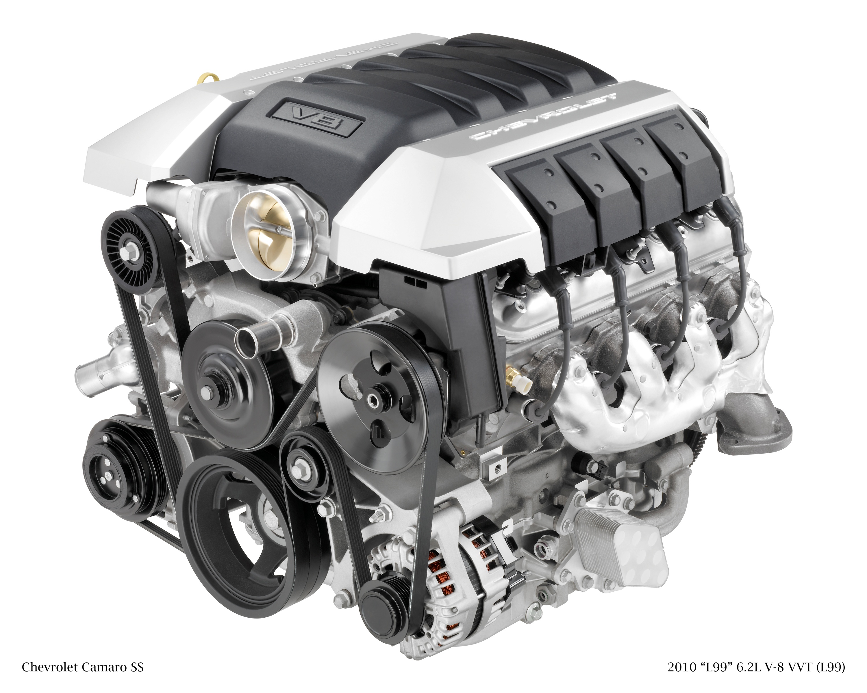
The Gen IV LS3 enjoyed an even larger bore – increased up to 4.065-inches -- to produce 6.2L. When introduced in the fifth generation Camaro, this larger engine came in two configurations; either as the LS3 with a manual transmission, or as the L99 6.2L engine with an automatic. The L99 came with both VVT and another engineering twist labeled Active Fuel Management (AFM), which is GM’s version of displacement on demand that under light load disables four cylinders to improve fuel economy.
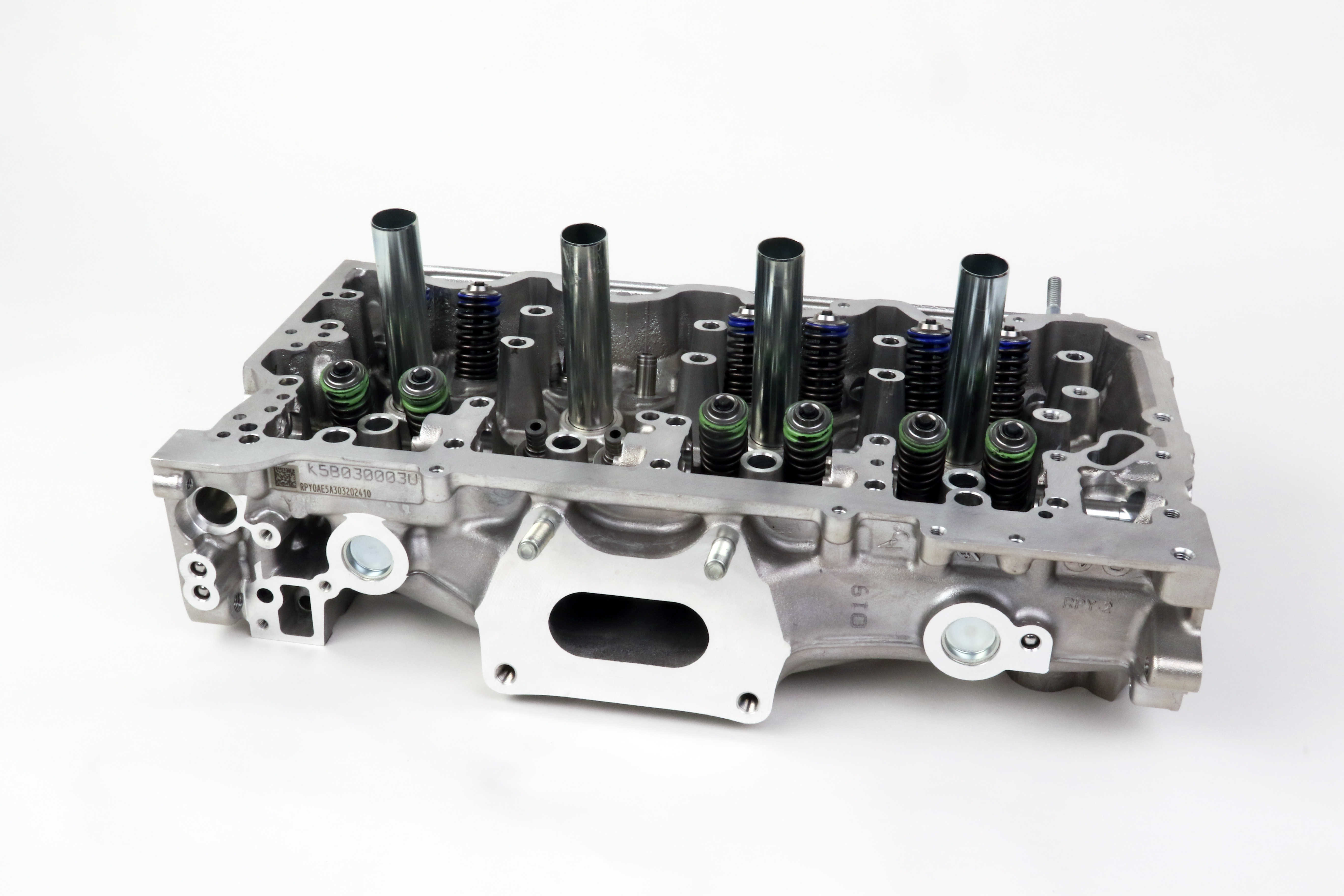
Both the intake and exhaust valve lifters in the four AFM cylinders can be disabled by application of oil pressure that moves a pin that allows the piston inside the lifter to move downward while the lifter body moves upward, following the cam lobe. This disables the lifter so that the valves in these cylinders do not open. AFM lifters are easy to spot as they include a large coil spring that sits atop the lifter. Spark is also disabled in the AFM cylinders. All of this takes around 20 milliseconds to accomplish and is literally seamless to the driver.
Looking for LS Pistons? Click here to see the full JE Pistons Catalog!
Obviously with the complexity and additional components required for both VVT and AFM, these improvements also limit the cam timing changes that can be made. So the aftermarket has responded by offering both VVT and AFM delete kits that will replace the lifters and the cam phaser so that a performance camshaft can be added.
With this quick overview completed through Gen IV, we can now dive into the major individual parts to give you a closer look at both features and interchangeability of each of these components.
Pistons
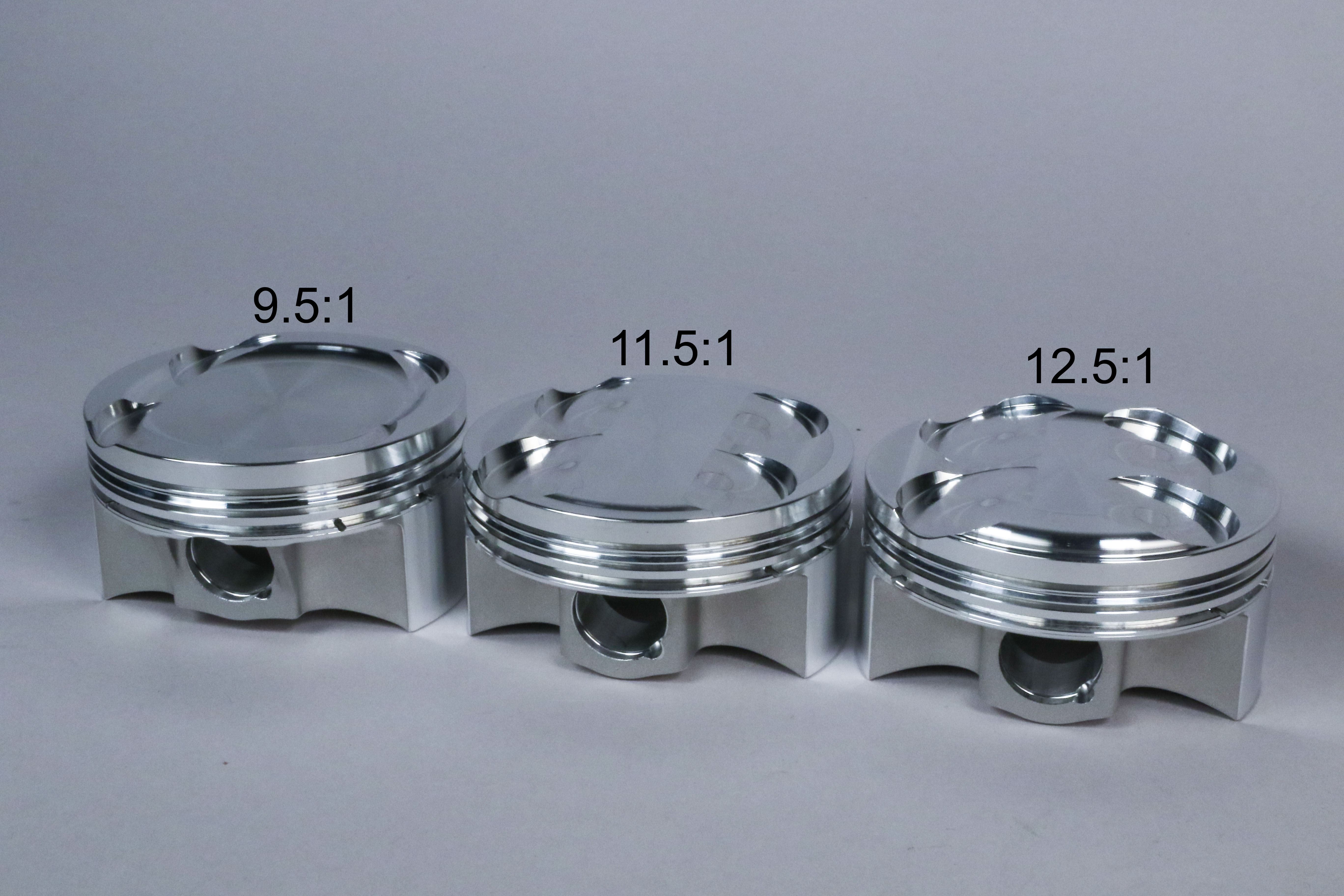
With a variety of displacements and crank strokes, there is an equally lengthy list of factory piston configurations. With only a few exceptions, the majority of LS pistons are eutectic – meaning they are a silicon alloy but still just cast pistons. Now with the LS engine clearing its 20th year in production, the stock pistons appear to be impressively durable. We’ve seen a 4.8L engine produce over 1,200 hp with cast pistons so they can certainly withstand cylinder pressure. It appears there are far more problems with connecting rods than with pistons.
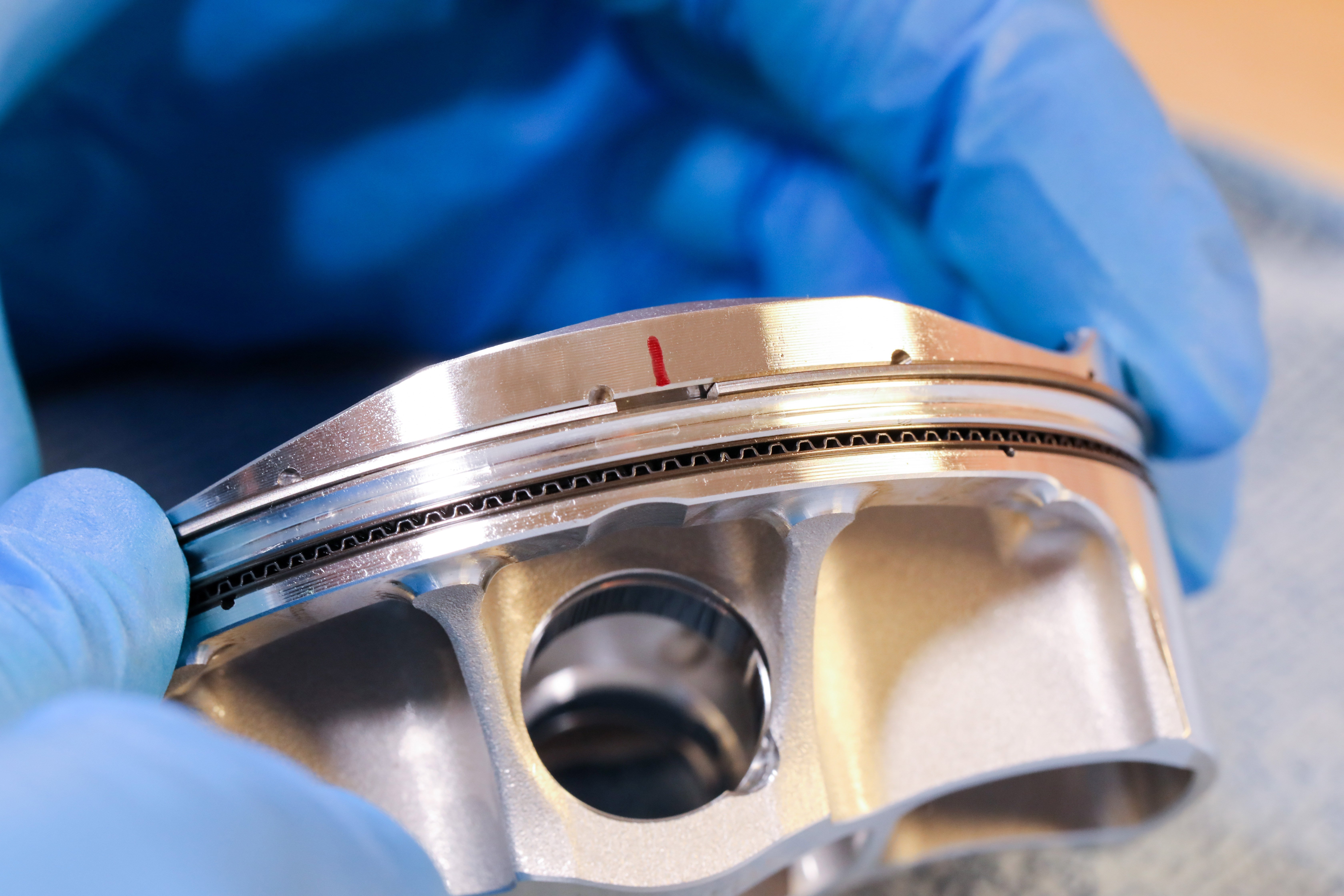
Production pistons use a 0.940-inch diameter wrist pin, slightly larger in diameter than a production small-block Chevy pin that is 0.927-inch. Perhaps the most significant evolutionary change with LS pistons has more to do with the ring package. The trend in the modern engine age has focused on narrower ring thicknesses in an attempt to improve both ring seal and reduce friction.
In the old days of the small-block Chevy, standard piston ring thickness was 5/64-inch (0.078-inch) top and second rings with a 3/16-inch (0.187-inch) ring package. In contrast, the LS1 first used in the ’97 Corvette dramatically trimmed these to a 1.5mm / 1.5mm / 3.0mm combination. In decimal units a 1.5mm ring is 0.059-inch while the 3.0mm oil ring slims down to 0.118-inch. Current Gen V engines now use even thinner rings.
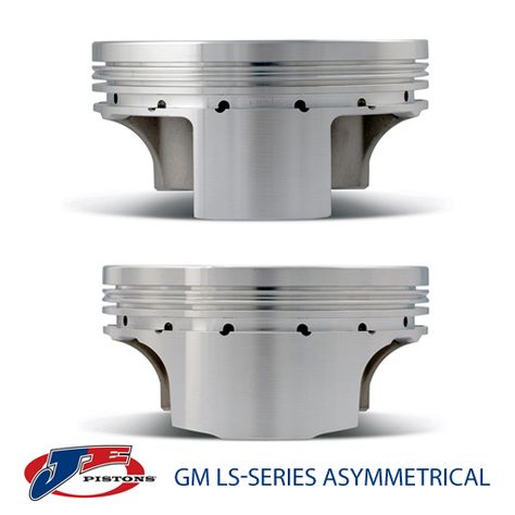
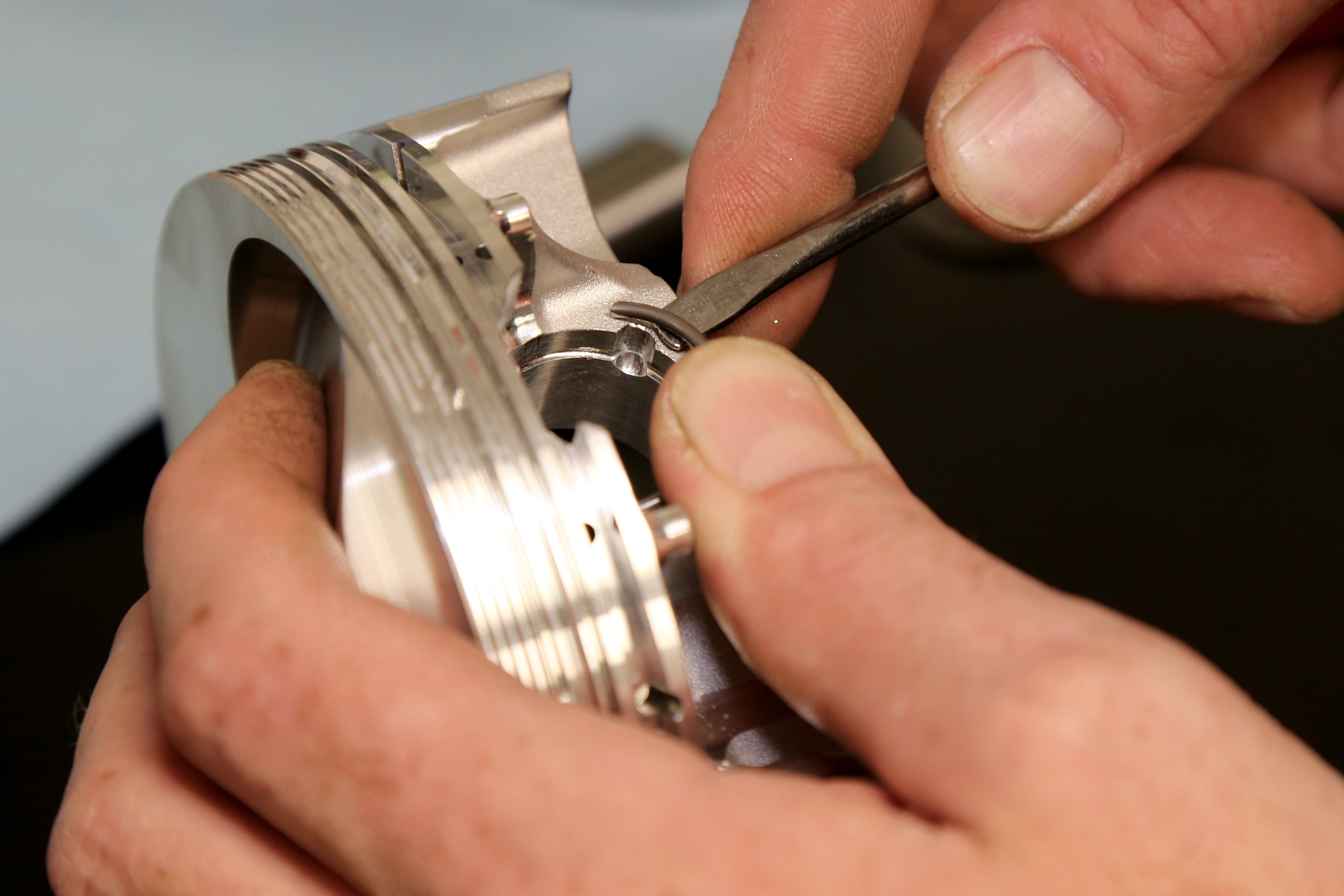
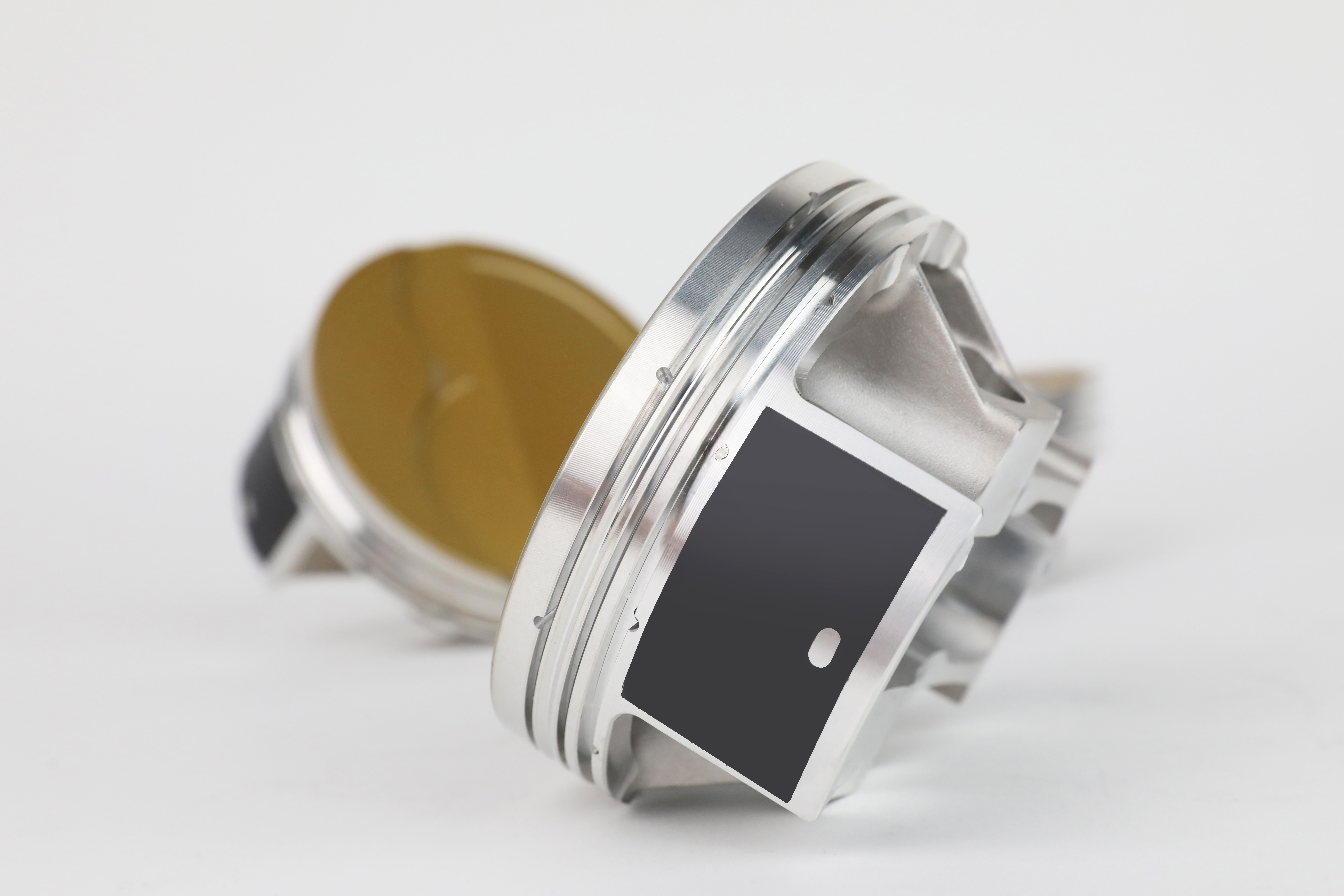
For performance applications, the best advice is to upgrade to a forged aluminum piston. Forged pistons offer strength and durability advantages far beyond the capability of a casting. While most enthusiasts tend to evaluate piston durability by using horsepower as their standard, the real load on any piston is the inertial forces created by engine speed. As rpm increases, the piston is subjected to dramatically higher loads applied at top and bottom dead center when the piston changes direction.
Looking for LS Pistons? Click here to see the full JE Pistons Catalog!
This is not a compressive load but rather a tensile load where the connecting rod attempts to yank the wrist pin out of the piston across TDC as an example. Just remember, doubling the rpm increases the load on the piston by a factor of four. This is why a given piston will live a long happy life at 6,000 rpm but with even a slight increase of rpm to perhaps 6,600 rpm, this might be enough to dramatically shorten its life span from months or years to mere hours or even minutes.
Cylinder Blocks
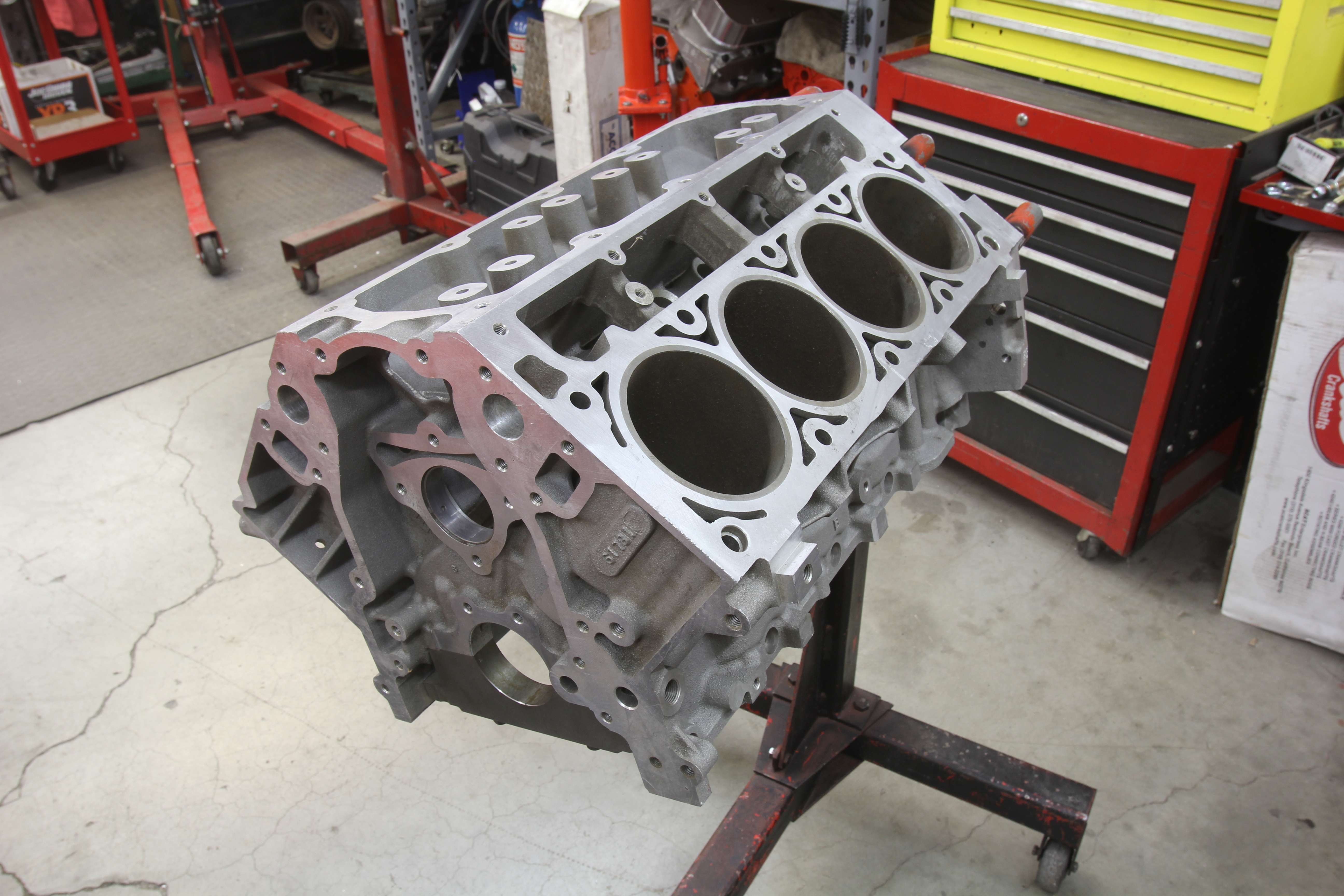
We’ll run through the cylinder blocks first by identifying them as either cast iron or aluminum. There will be a far greater selection of iron engines available in the used market compared to aluminum engines because iron truck engine production is so much higher. One of the biggest differences from the old small-block is the reduction of the number of head bolts per bank from 17 bolts to 10. The LS deck height also grew from the small-block’s 9.025 to the LS standard of 9.240 inches, making it slightly taller.
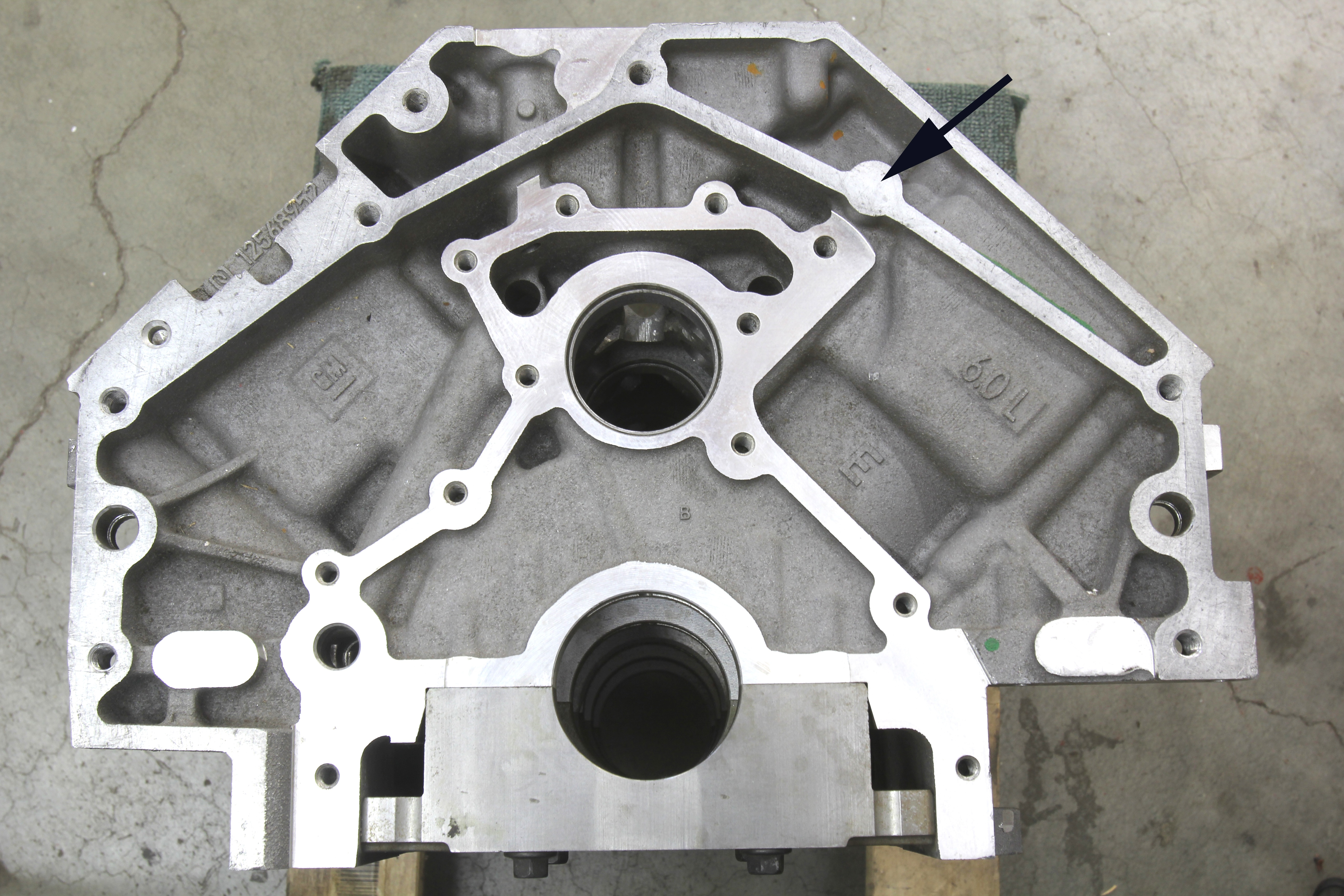
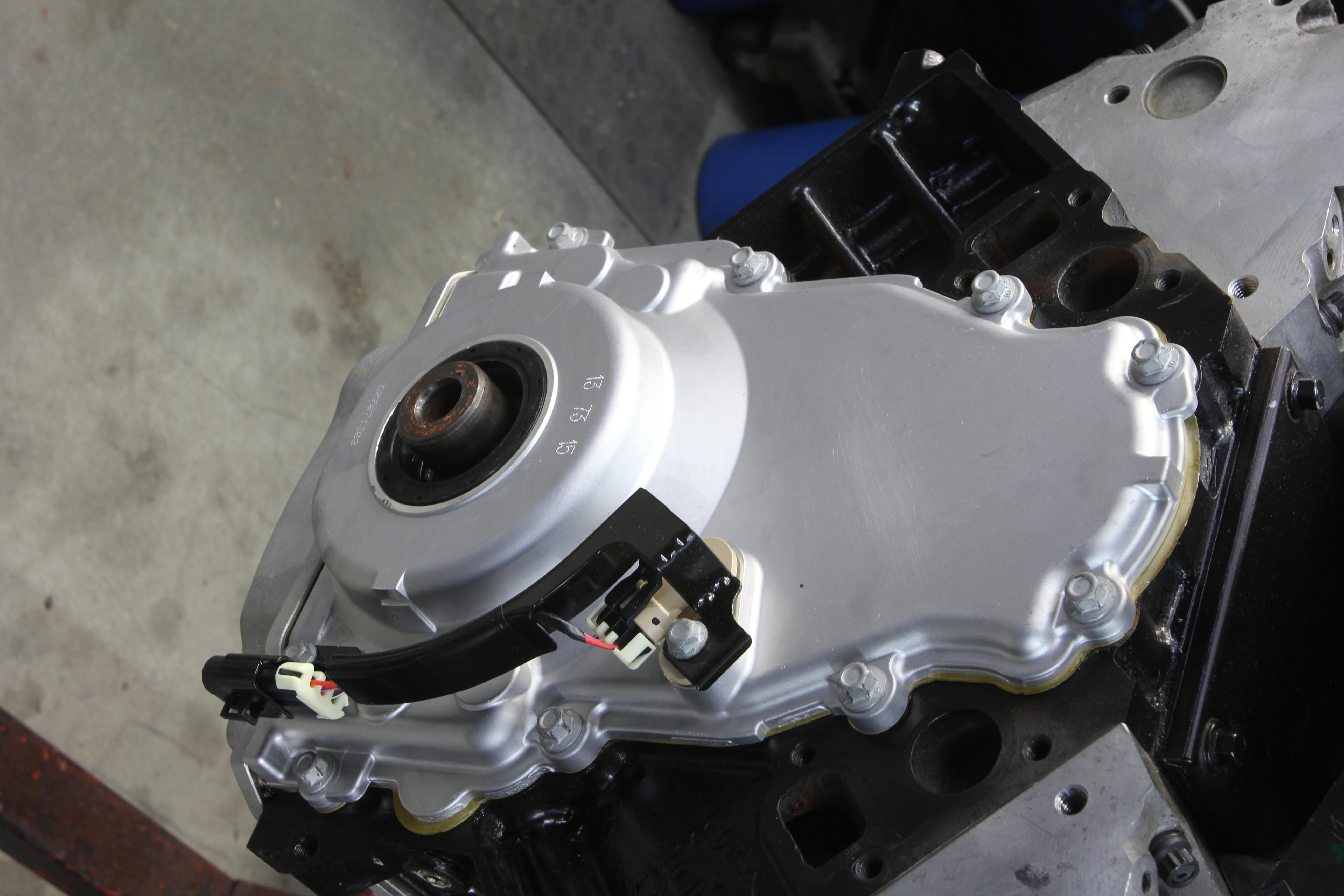
The easiest way to identify a Gen III block (either iron or aluminum) is by the cam sensor located at the top of the block directly behind the lifter gallery cover. The crank sensor is located in the same spot for both Gen III and IV engines but the sensor colors change. The Gen III sensor is black, while the Gen IV version is grey.
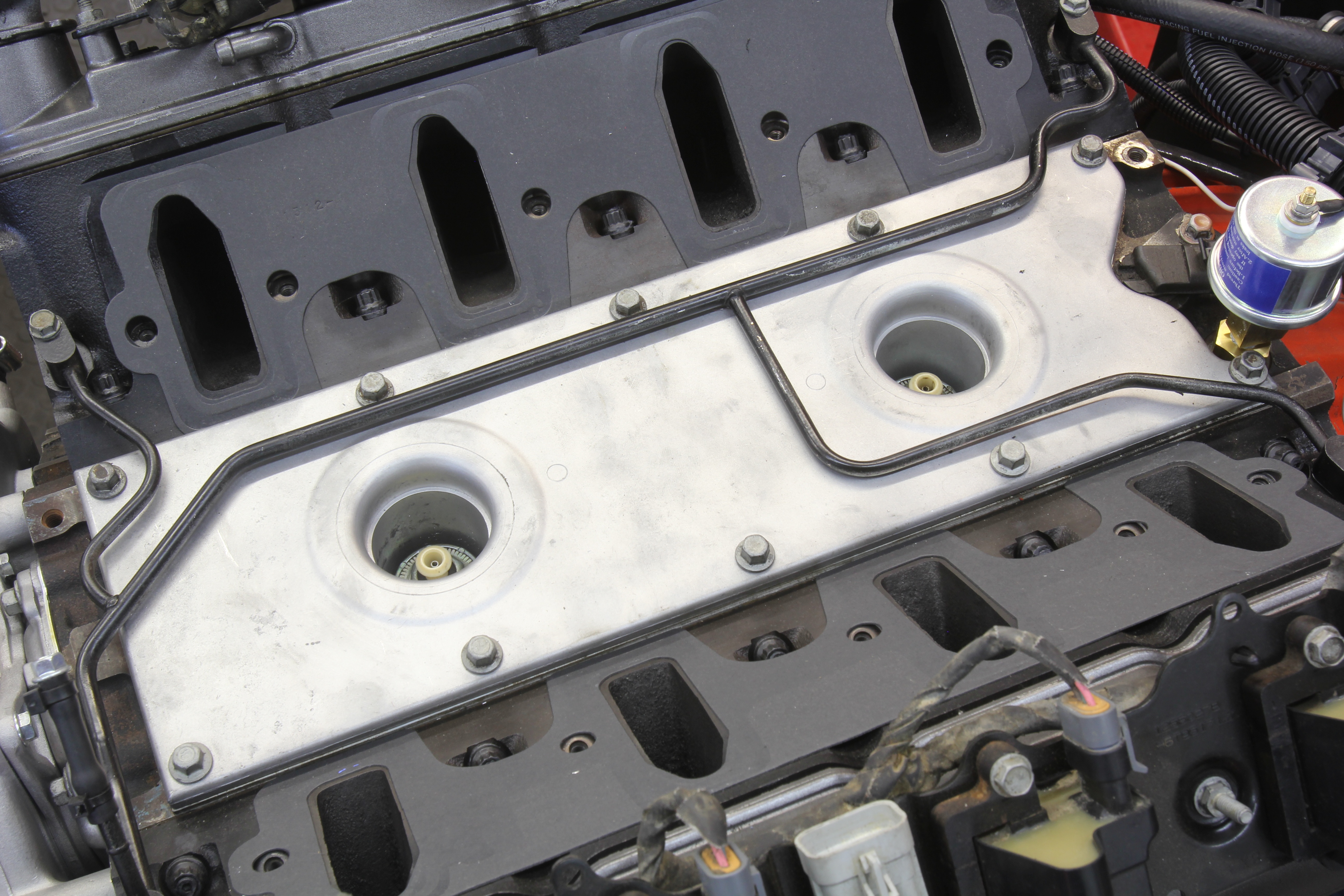
While many Gen III and IV parts do interchange, the early Gen III blocks did undergo a few minor changes. Early ’97-’99 blocks used two holes underneath the rear cover for an oil passage that is less desirable than later 2000-newer Gen III’s that used a more open slot directly above the cam bore that connects the oil passages in the back of the block. The 2003 and earlier iron and aluminum blocks used two different head bolt lengths while all later blocks changed to a common length.
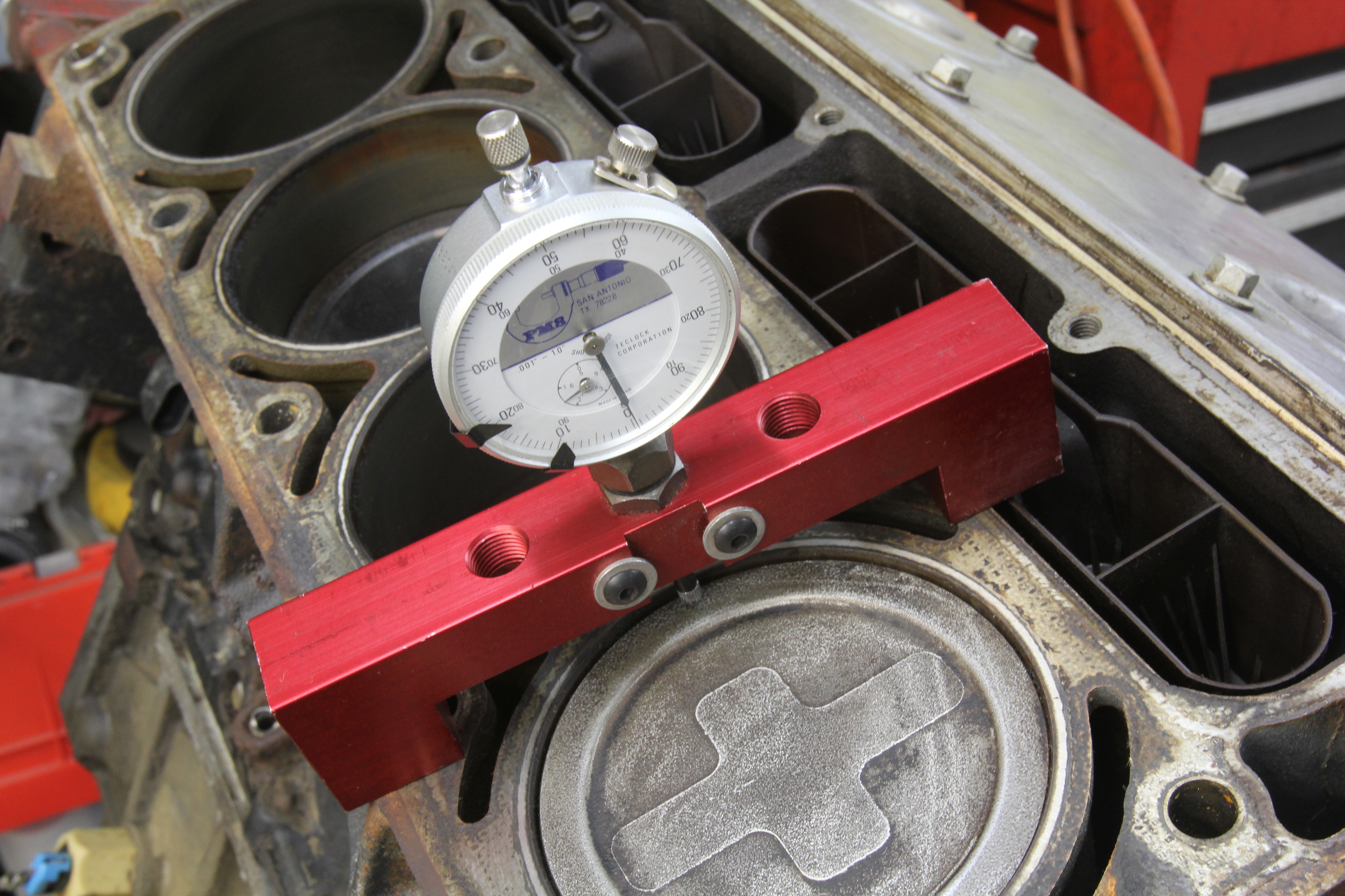
Cylinder bore diameter is perhaps the most obvious differentiator with regard to iron or aluminum blocks. The iron 4.8L and 5.3L blocks share a common bore at 3.78 inches. Next up in size is the original 5.7L (345ci) at 3.898. One advantage to the iron blocks is they enjoy a much greater wall thickness allowing larger overbores. The aluminum blocks are cast with a thin iron liner that restricts overbores to no more than 0.010-inch. This is why the most popular way to increase displacement with aluminum block engines is by increasing stroke. We’ll deal with that in our section on crankshafts.
As an example of mixing rotating parts, it’s possible to replace the 4.8L crankshaft with a longer LS1 crank (3.62- vs. 3.26-inch stroke) and machine that stock 4.8L bore to 3.898-inches (stock 5.7L piston diameter) and use a standard bore LS1 rotating assembly to construct a budget-based 5.7L engine that masquerades as a 4.8L. For the larger 4.00-inch bore, iron 6.0L truck blocks, they can be successfully bored to 4.065 (standard LS3 bore size).
Any planned large over-bore block should first be sonic tested for wall thickness. A general rule is to retain a minimum wall thickness of 0.220-inch on the thrust side of the cylinder wall, although that number is often successfully ignored. The thrust sides of any V-style engine are the inboard wall of the left (driver) side and the outboard wall of the right (passenger) side of the block. During combustion, it is these sides of the cylinder wall that are exposed to greater piston loads.
Because the LS family can make such great power, even the factory realized that added cylinder pressure also meant added heat. One solution that evolved out of racing was to keep the pistons cool by adding oil squirters. The LS7 7.0L engine was the production LS engine debut for this technology, with curved discharge tubes bolted to the bottom of the cylinders in the crankcase. By directing a small stream of oil into the back side of the piston, this would pull additional heat out of the piston crown, improving durability under high load.
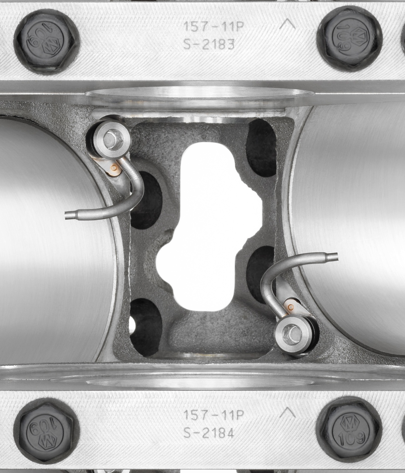
Since then, this idea has been used on both the supercharged LSA 6.2L engine used in the Cadillac CTS-V and ZL1 Camaros as well as the supercharged LS9 Corvette engine.
Crankshafts
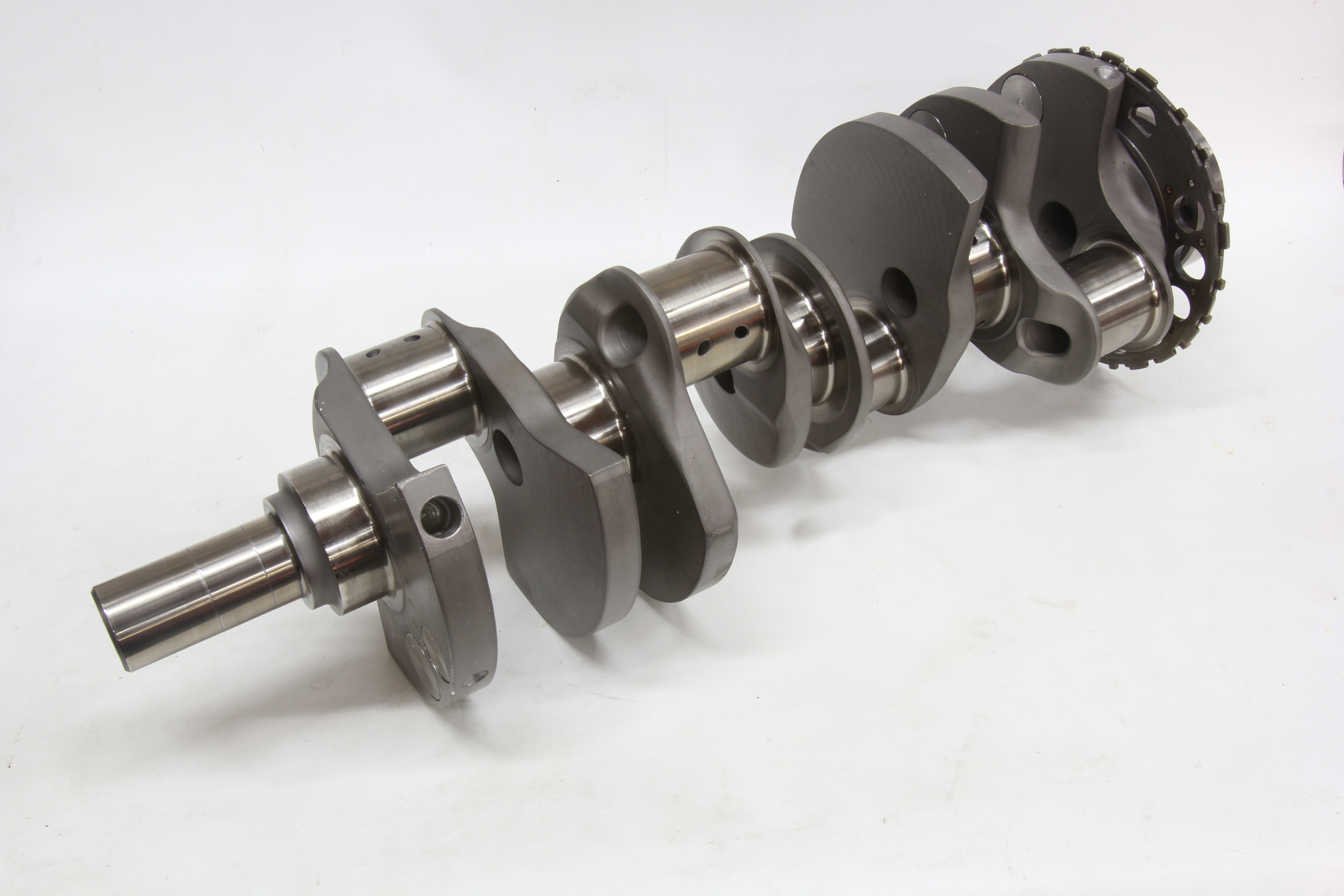
The majority of GM LS engines employ a standard 3.62-inch stroke crankshaft. The smaller displacement 4.8L uses a shorter 3.26-inch stroke crank and the 427 LS7 stands on the longest, 4.00-inch stroke version. All LS crankshafts will physically interchange, but there are crucial details that can affect how well these swaps will actually perform.
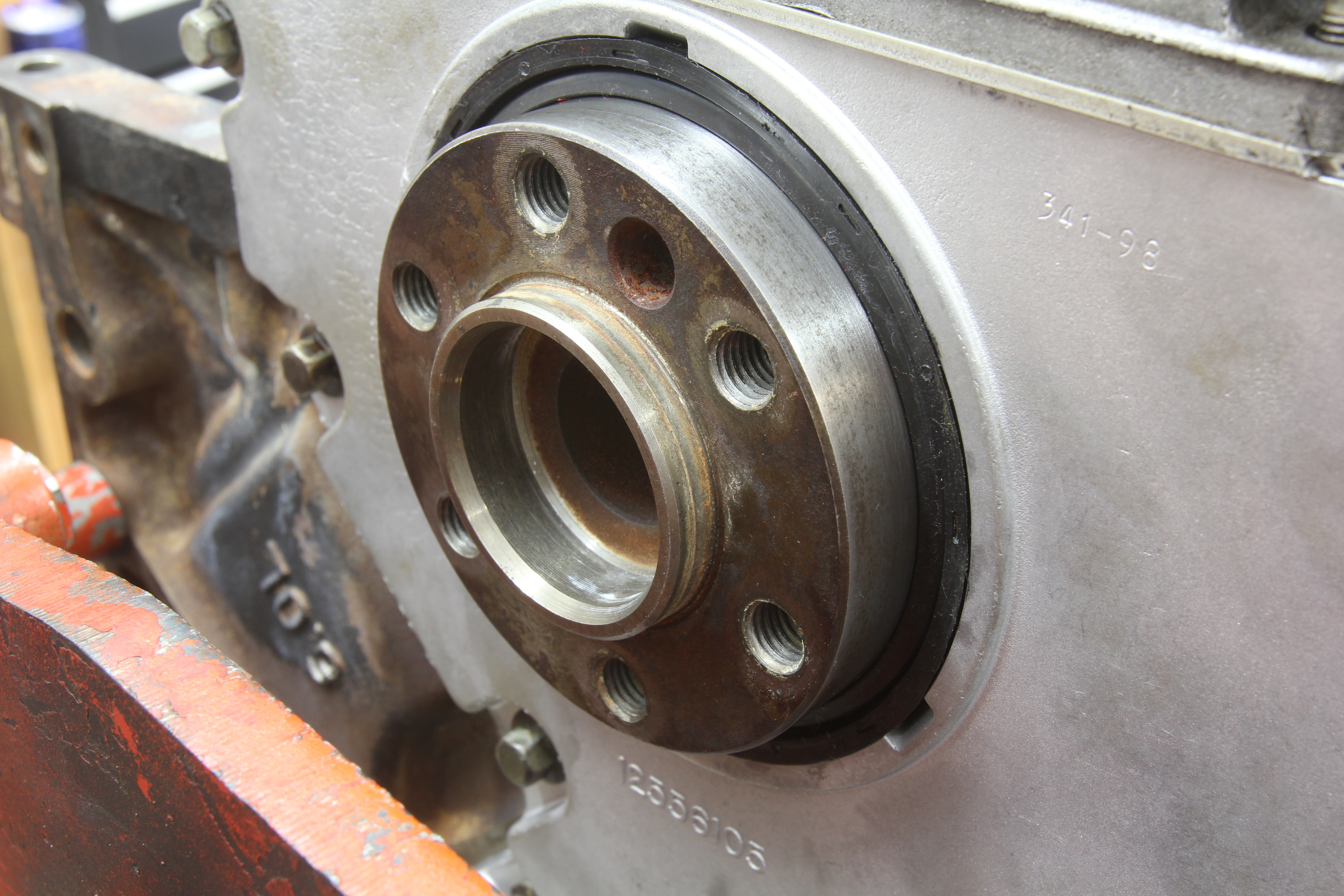
We’ll start with the simple stuff, like the conversion from Gen III’s 24x crank wheel to Gen IV’s 58x wheel. What many enthusiasts don’t realize is that these wheels can be removed and replaced, but it’s a job best left to professionals since the wheel’s location is critical. Replacement reluctor wheels are available through any GM dealer.
The next biggest hurdle for production engine swappers is the size of the counterweight. The obscure detail is that nearly all 5.3, 5.7, and 6.0 Gen III cranks use the same 12552216 casting number, so it’s difficult to quickly differentiate a 5.3L crank from a 6.0L. This is important if you are mixing and matching LS engine parts because a 4.00-inch bore 6.0L piston weighs much more than its smaller 5.3L cousin. This means the counterweight in the crankshaft must carry additional weight, known as the bob weight, to compensate for the heavier piston. While you can use a 5.7L crank in a 6.0L application, it will require additional heavy metal in the counterweights to add bob weight to balance properly. This will substantially increase the cost of balancing the rotating assembly because heavy metal is expensive.
According to some reports we’ve seen, it is possible to identify a 5.7L LS1 crank by its rifle-drilled center that apparently was not employed on Gen III truck cranks. The only way to know for sure whether you can mix and match these cranks is to have them checked by your local engine balancer.
Another minor crankshaft difference occurs with any production engine running a dry sump. The LS7 7.0L for example, employs not only a unique 4.00-inch stroke crank but the snout is 0.886-inch longer to accommodate the dry sump pump. The crank can be used with wet sump engines, but this distance must be machined off the front of the snout.
The LSA is the supercharged 6.2L powerplant used in the Cadillac CTS-V and ZL1 Camaro. Among this engine’s upgrades to accommodate the supercharger is a forged steel, 3.62-inch stroke crankshaft. The even better news is that this crank sells for less than $700 (PN 12641691) from Chevrolet Performance shops like Scoggin-Dickey and it will drop right into any Gen IV 58X LS block. It employs a stock length snout because this is a wet-sump engine, but one significant change is its 8-bolt crankshaft flange that will demand a matching LSA flexplate or flywheel. This is an excellent factory forged crank that is affordably priced.
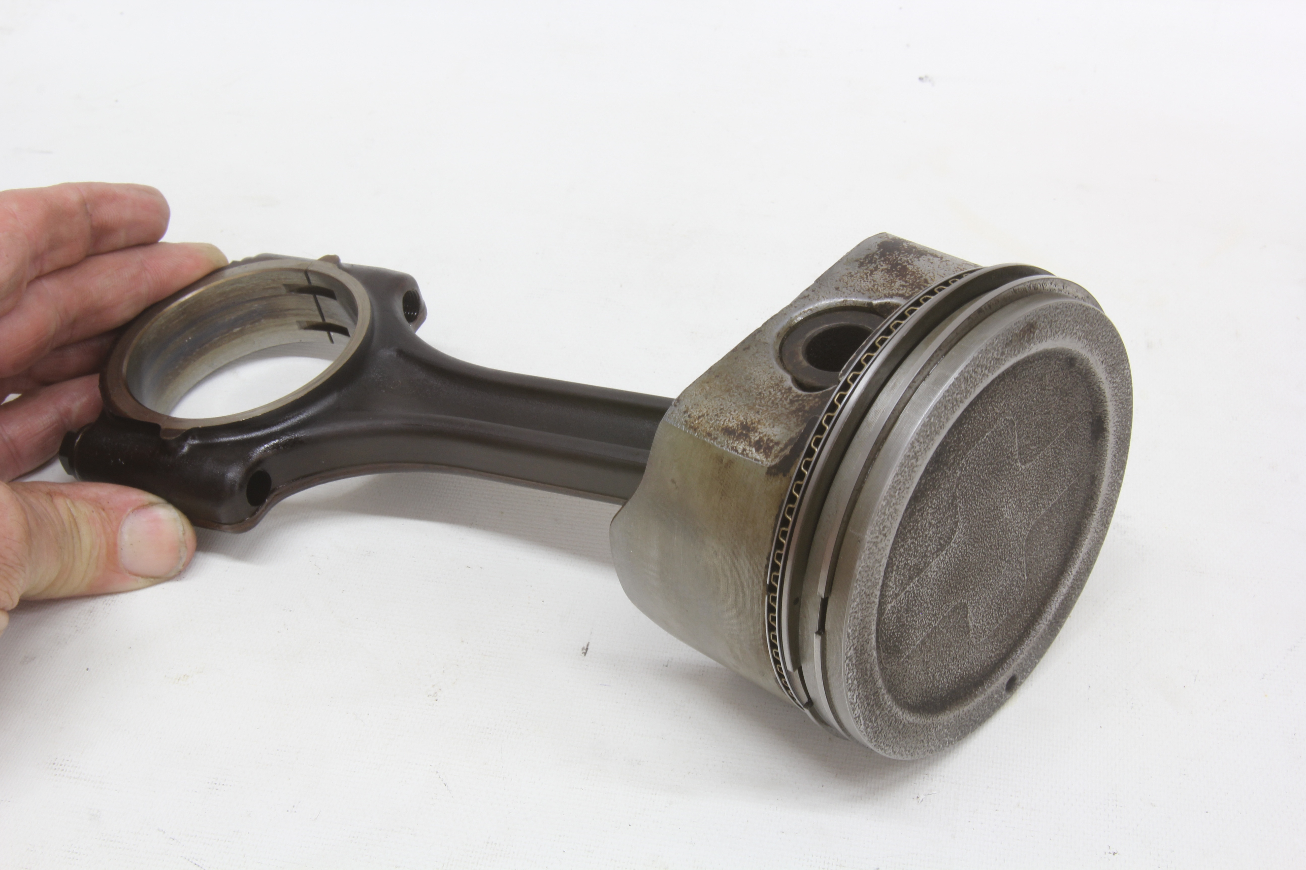
Connecting Rods
In a significant deviation from the normal die-forged steel connecting rod used forever in the small-block Chevy, GM LS engineers instead chose to outfit all LS engines (except the LS7 – we’ll get to that) with powdered metal connecting rods. While still technically a forged steel piece, the process differs, starting with powdered metal. This is forged in melting process to create the basic rod. A slight depression is created parallel with the intended cap parting line and then the cap is fractured to separate it from the main body.
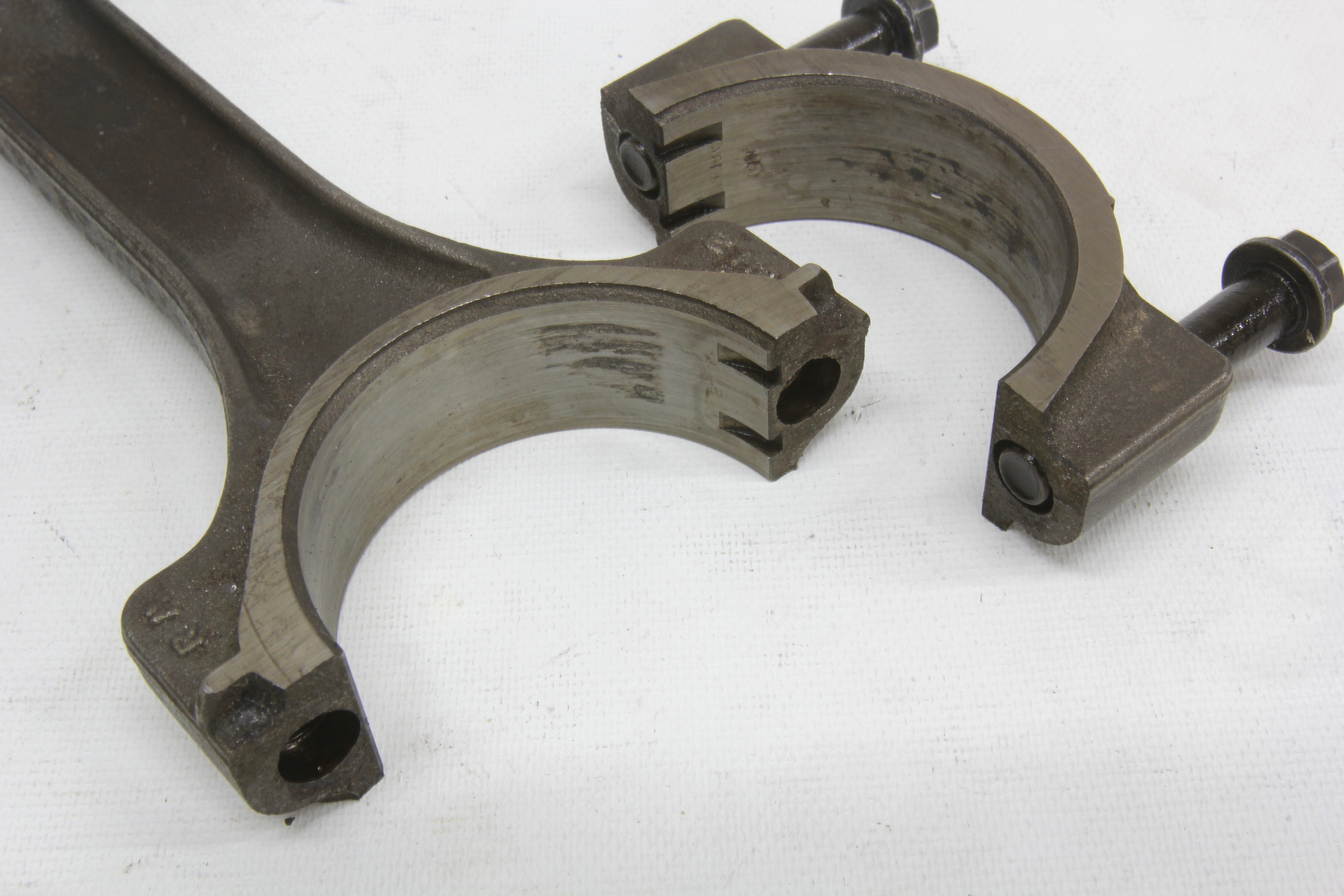
This is the reason these rods are often referred to as fractured cap (not cracked – engineers abhor that term). The advantage is that this fracture creates hundreds of peaks and valleys that serve to accurately locate the cap. This helps prevent “cap walk” which can occur with rods with smooth mating surfaces under extreme loads.
Final machine work includes drilling and tapping for capscrew fasteners and finish machining for its net inside diameter. Ironically, the rod then uses the same connecting rod bearing as its large journal small-block Chevy ancestor. This is a little technical tidbit you can drop at dinner parties to get the conversation started!
The disadvantage of the fractured cap technology is it prevents the time-honored big-end rebuilding technique where the rod cap is machined flat to reduce the i.d. and then honed to the proper dimension. This process cannot be accomplished with fractured caps. There is a shortcut some machine shops use where they bead blast the fractured areas to reduce the big end i.d. roughly about 0.001-inch. This allows the machinist to hone the rods to the proper i.d. The problem with this approach is that the bead blasting rounds off the peaks and could potentially allow the cap to move. For a high performance application, it should be obvious why this is not a good idea.
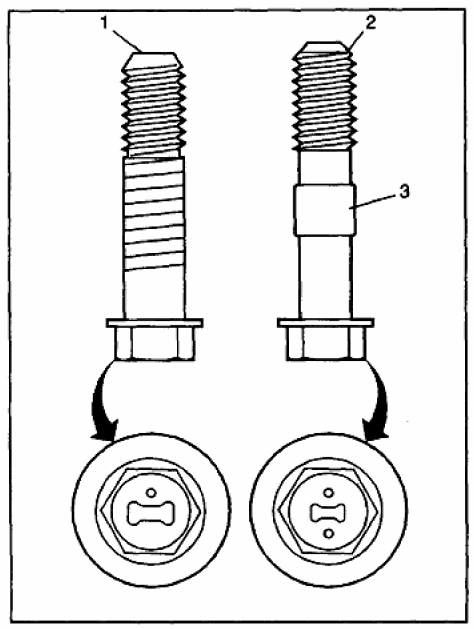
From our research, it appears there are at least three different rod bolts, and all appear to use different torque specs. Version I used knurling to position the bolt in the rod. Version II used a small raised area in the middle of the bolt to position it in the main portion of the rod and offers a pair of marks on the head. A third bolt was used on LS6 engines and appears to be of higher quality. This brings up issues of whether there could be changes to the big end of the bore with a higher torque value applied to the bolt. We’ve not done this test so we can’t comment. But it is likely that with a higher torque value, the bearing clearance value may change.
All LS rods are 6.098 inches in length except for the 4.8L truck engines and the LS7. The 4.8L rod is longer at 6.298 inches to allow GM to use the same compression height between the 4.8L and 5.3L even though, as we’ve seen, the 4.8L and 5.3L pistons are not the same.
The LS7 connecting rod caused quite a stir in performance circles when that 7.0L engine debuted. This was the first titanium connecting rod ever in a production domestic engine and its uniqueness does not end with its material. Yes, it’s lighter but it’s also shorter (basically 0.030-inch) than the production steel rod with a 6.067-inch center-to-center length. While it might appear attractive for its lighter weight, there are fundamental differences in small-end width that will require a custom piston to accommodate their shorter length. Plus, the word on the street is that these rods are not happy with higher than the stock 7,000 rpm LS7 redline. For a high-rpm performance engine, any number of aftermarket 4340 steel rods will be less expensive, easier to work with, and provide fewer balance issues.
Because the stock powdered metal rods are not designed for easy rebuilding, the recommendation for any performance street engine over 500 horsepower would be to invest in a set of aftermarket 4340 steel rods instead of relying on the somewhat questionable strength of the powered metal stockers. Plus, aftermarket rods come in longer lengths such as 6.125, allowing shorter and lighter pistons.
Camshafts
This is an area that could encompass an entire story all by itself so we’ll only be able to hit the factory high points. The LS engine design began with a much more robust 55mm journal diameter (2.165-inches) versus the standard small-block Chevy size of 1.868-inches. This larger journal not only adds strength but also improves valvetrain dynamics. All factory LS engines use hydraulic roller lifters with the same body diameter (0.842-inch) as its small-block predecessor. These lifters are not, however, interchangeable.
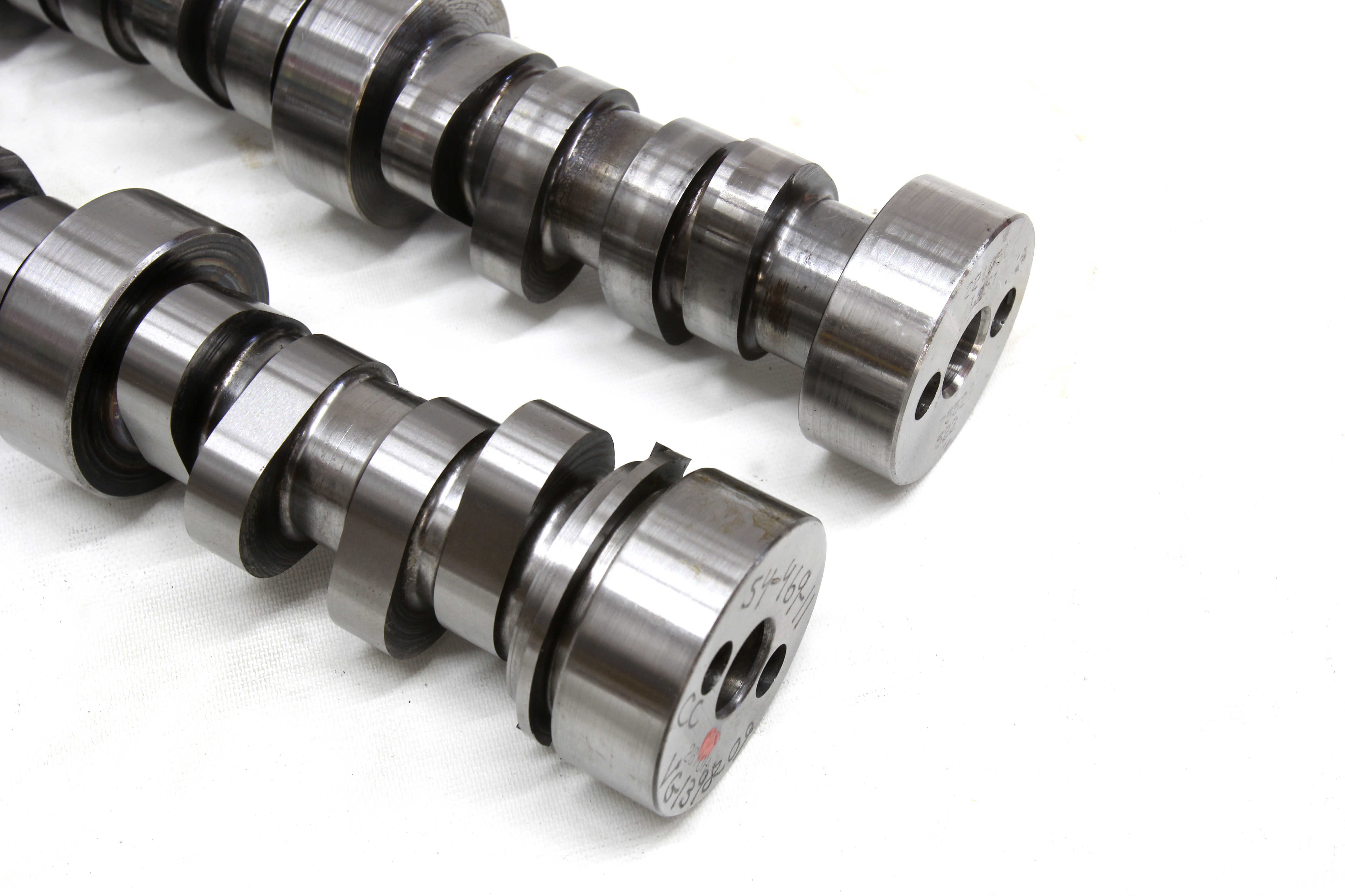
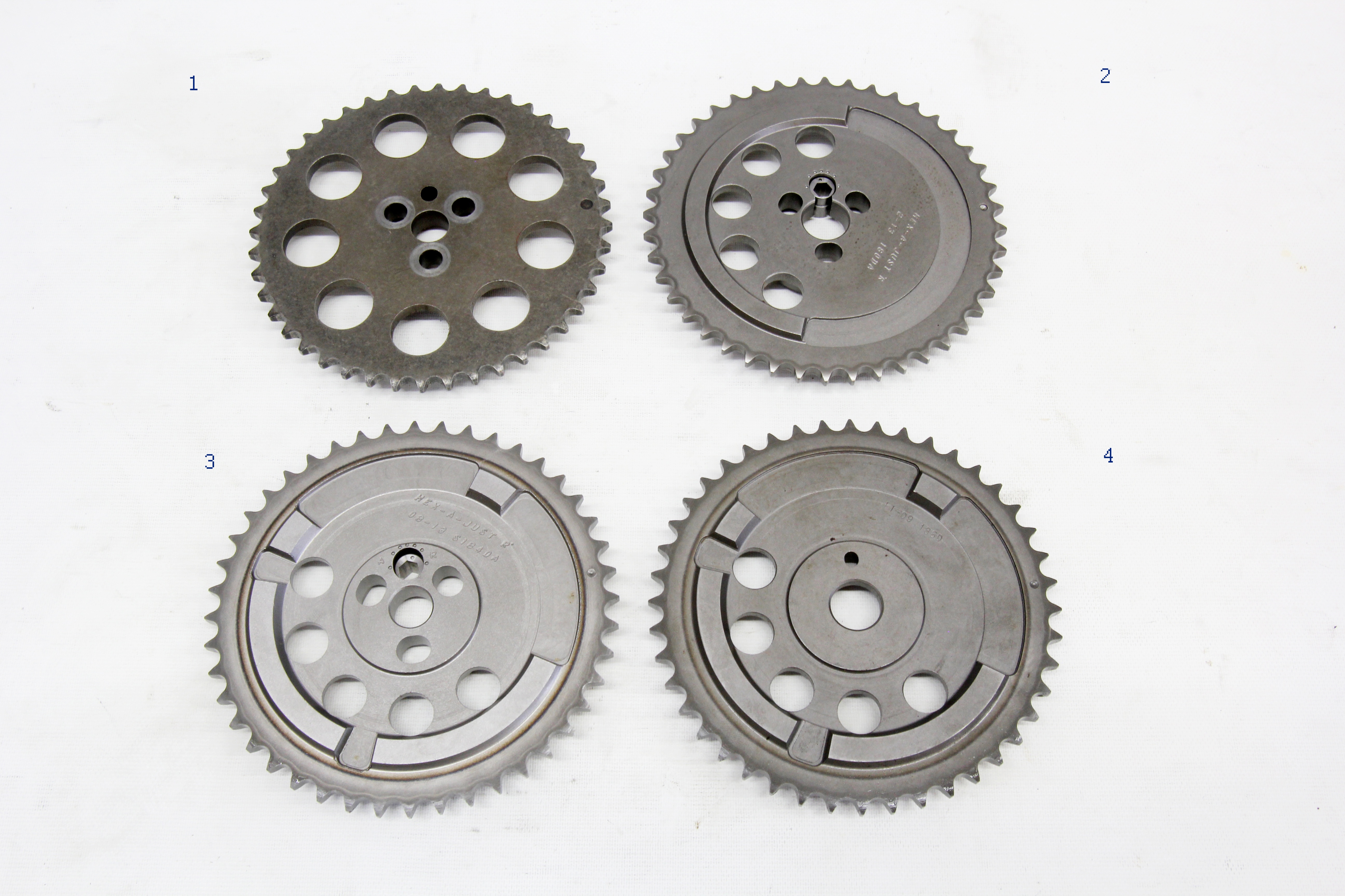
Gen III engines place the cam sensor trigger wheel on the back of the camshaft. Then with the 58x Gen IV engines, the cam sensor moved to the front of the engine and used the cam drive gear as its shutter wheel. Other significant changes involved the Gen IV cams moving from the traditional 3-bolt cam gear attachment method to a simpler one-bolt affair. It is possible to retrofit a 3-bolt cam to a later engine as long as you follow all the caveats.
Beginning in 2004 with Gen IV engines, GM introduced a couple of really interesting developments in an attempt to continue to improve this simple 2-valve engine’s superior power while also enhancing drivability, low-speed torque, and fuel mileage. The first move was to a technology called VVT or variable valve timing. Essentially this system uses a hydraulically-actuated, electronically-controlled cam phaser located on the front of the cam that allows the ECU to move the camshaft’s centerline through a range of as much as 62 degrees relative to the crank position. Among the multiple advantages is the cam can be advanced at idle and low speed to improve idle stability and then, depending upon load, rpm, and throttle position, the cam can be retarded to improve power. By retarding the cam, this delays the intake closing point at higher engine speeds which will aid cylinder filling.
Most of this cam movement is used to both improve idle quality and to reduce emissions, but it does offer some performance advantages that most enthusiasts don’t realize. GM then quickly followed VVT with AFM. Wading through the alphabet soup, AFM is Active Fuel Management, which is GM-speak for cylinder deactivation. Here’s how it works.
Looking for LS Pistons? Click here to see the full JE Pistons Catalog!
The whole AFM game revolves around a set of intake and exhaust lifters that are essentially lost motion devices. Traditionally, lifters transfer the rotary eccentric motion of a camshaft lobe into linear or up-down movement. With AFM, the lifter still follows the cam lobe, but with a millisecond trigger, a pin is activated, allowing the lifter to continue to move but the internal hydraulic lifter piston portion of the lifter remains stationary inside the lifter body. Valve spring pressure ensures the intake and exhaust valves remained closed, so pumping losses are minimized.
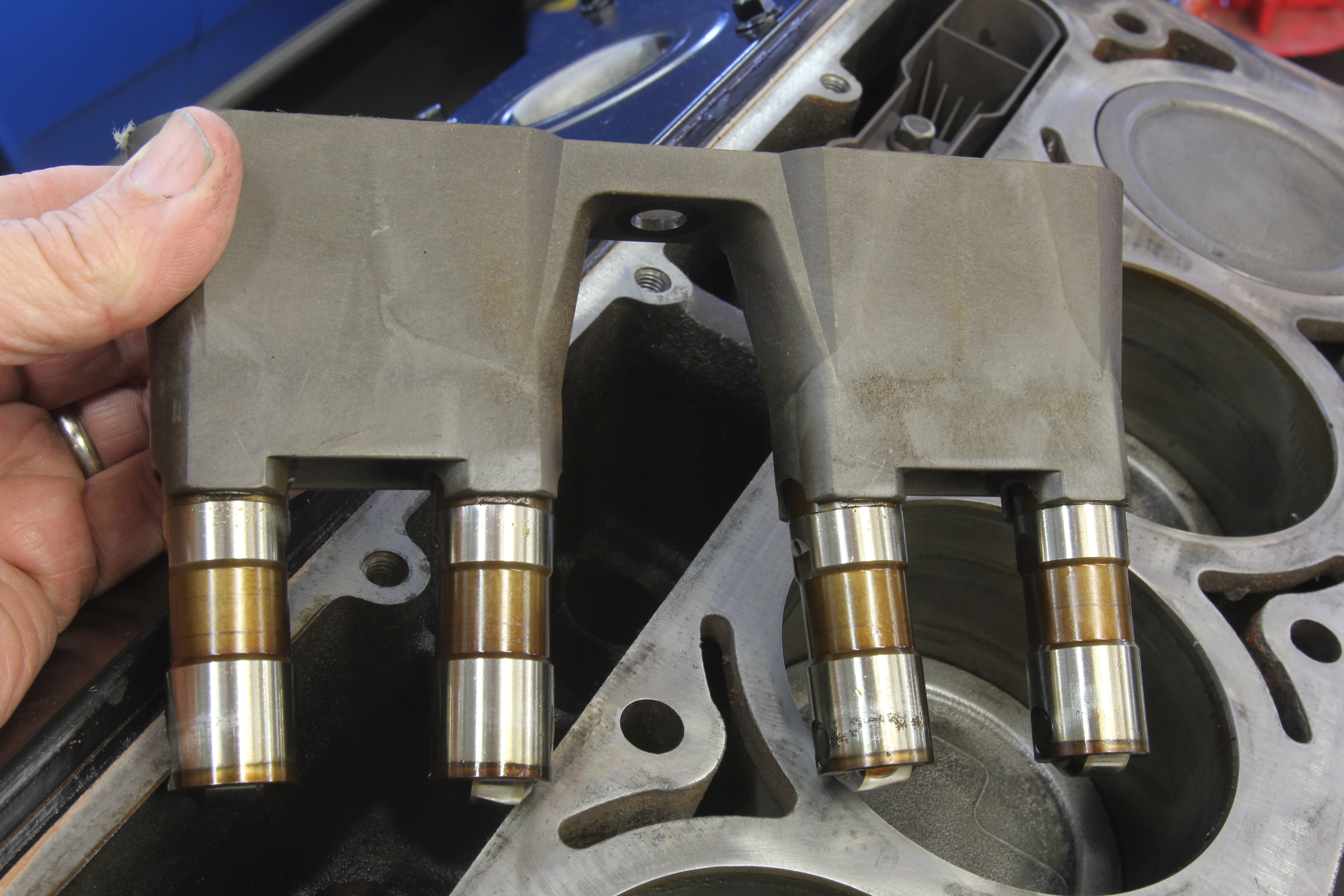
This cylinder deactivation is accomplished on alternate cylinders in the firing order (1, 4, 6, and 7) to produce a four-cylinder engine for low-rpm, light-load cruising applications such as freeway driving. This improves fuel mileage since these deactivated cylinders are also not supplied with fuel or spark. The conversion between four and eight cylinders is imperceptible to the driver but does result in measurable fuel mileage improvements. For those with a penchant for performance, there are several companies already offering AFM delete kits since these lifters are heavier than stock and prone to malfunctioning when pushed into higher engine speeds. The lifters are also susceptible to problems due to debris screens clogging up in high mileage applications. Besides the mechanical aspect, disabling the AFM also requires software changes.
Back on the performance side of things, GM has produced an absolute wealth of different production camshafts, most of which are very tame, but there are a couple of worthy candidates for street engines. These are mostly suggestions for mild power improvements for truck engines like the 5.3L and 6.0L engines with OE cams that offer very short duration and mild lift. We’ve included a short chart of selected factory LS camshafts listing their duration at 0.050 numbers, valve lift, and the lobe separation angle (LSA).
It might appear that the best cam would be the LS7 profile used in the 7.0L Corvette engine. But our experience has shown that for mild street LS truck engines, like the LQ4 for example, the additional 15 degrees of intake duration and wider lobe separation angle tends to kill too much low speed torque. This is where mild street engines perform best, so killing perhaps 20 to 30 lb-ft of torque where the engine will spend a majority of its time just isn’t a good idea. Granted the longer duration cam will increase top-end power, but most often, the tradeoff isn’t worth the price of admission.
A much better choice for that same LQ4 6.0L truck engine or even a smaller 5.3L version would be the stock LS2 cam. This cam still offers increased duration over the stock version but also adds as much as 0.50-inch more valve lift. Swapping to this LS2 cam should be accompanied by improved valve springs as well. If you are considering this swap, keep in mind that the LS2 cam was part of the Gen IV configuration and will require converting to a front cam sensor. This involves purchasing a new LS2 cam cover and cam sensor along with a new cam drive gear with the appropriate sensor lugs. This is true when installing any Gen IV camshaft in a Gen III engine. This is because the Gen IV cams do not offer a cam sensor trigger at the rear of the cam like the Gen III cams.
Lubrication System
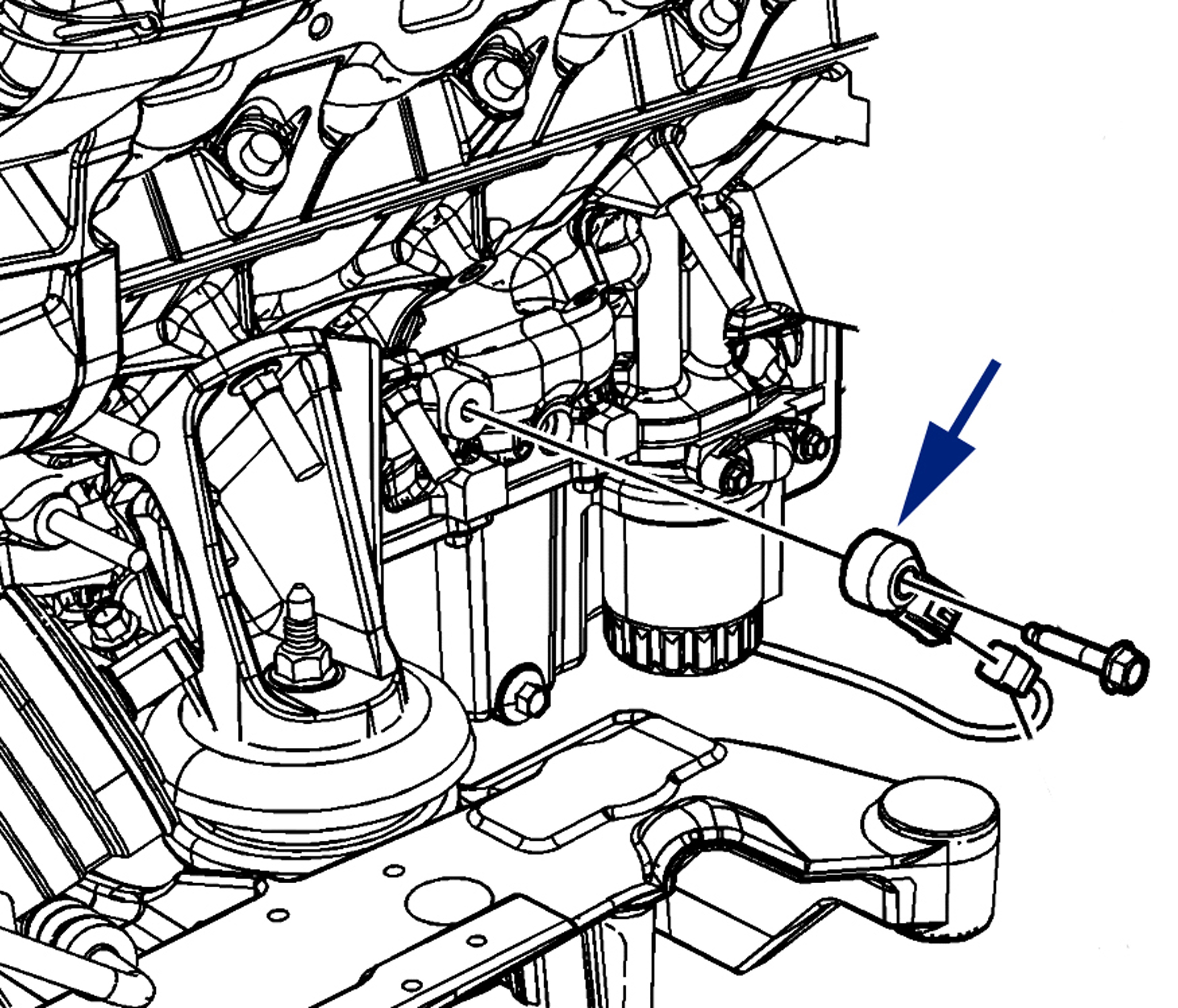
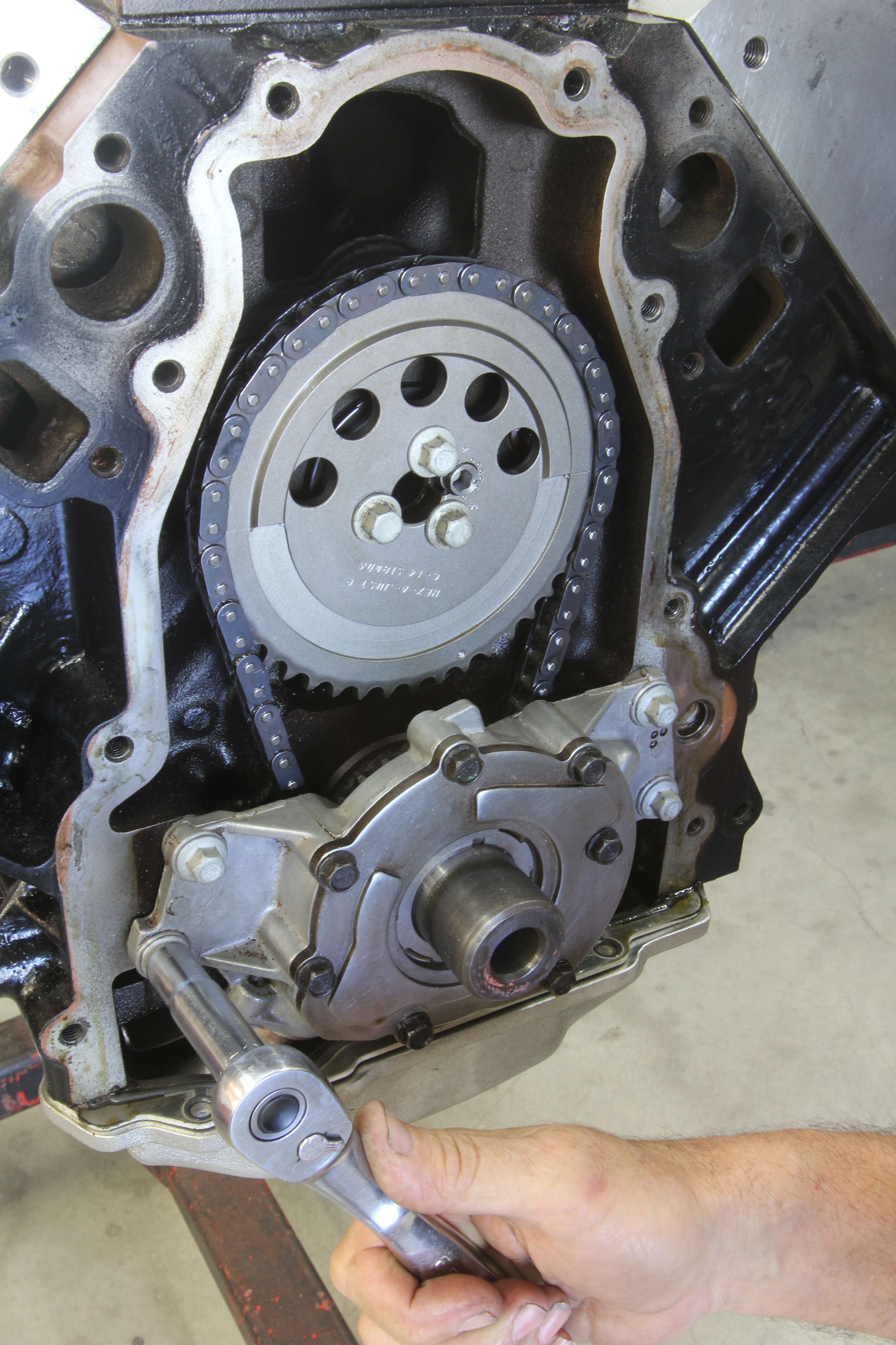
We will spend only a small amount of space on the lubrication system as this does not change much from Gen III to Gen IV engines. The most significant departure from the original Gen I small-block Chevy is the Gen III’s use of a crank-driven oil pump. This gerotor pump is placed just ahead of the timing set using a long pickup tube located at the rear of the engine pulling oil from the sump. Moving the oil pump eliminates load on the camshaft, but also spins the pump at full engine speed which can dry up a stock oil pan at elevated engine speeds – above 6,800 rpm.
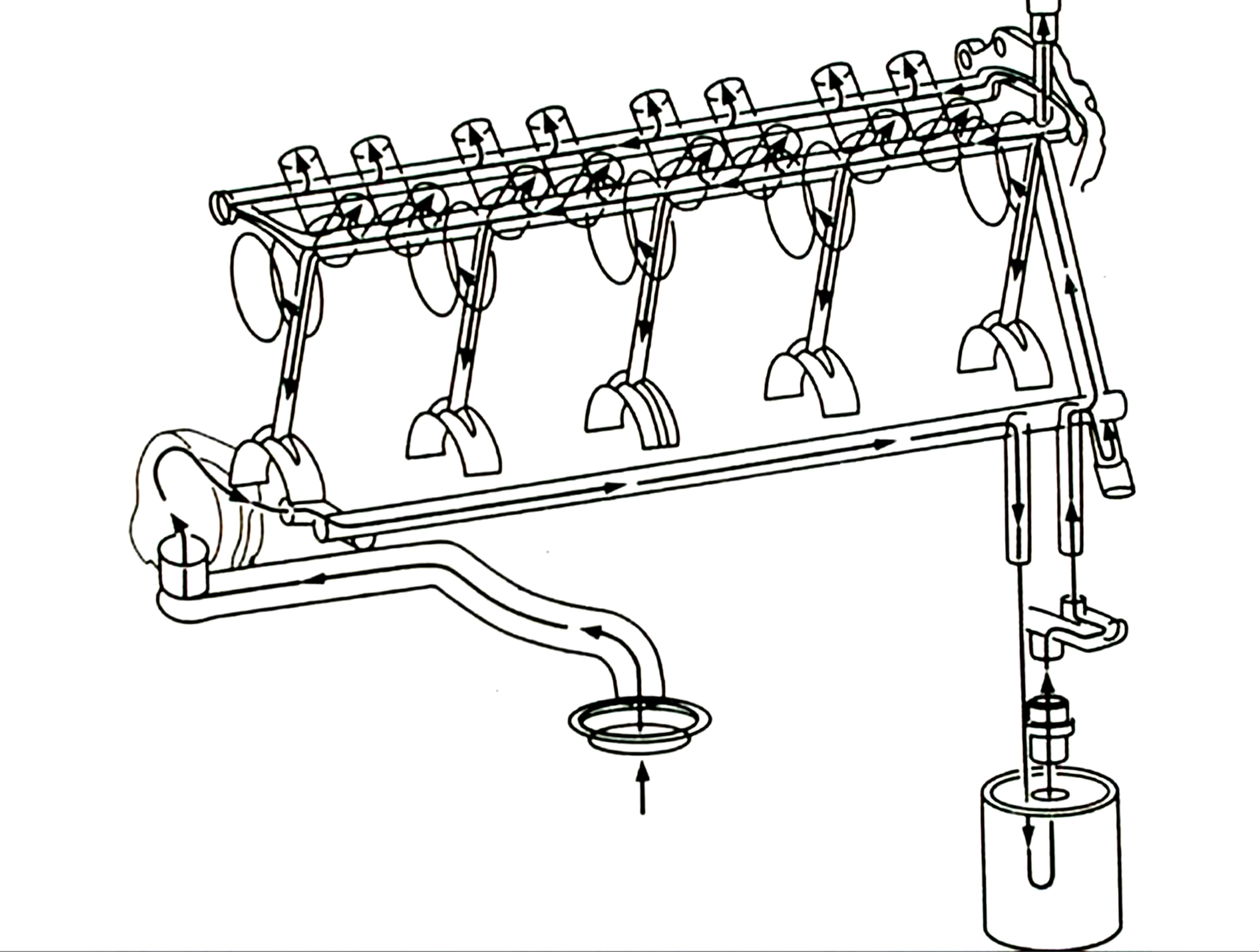
Like the small-block, the oiling system follows a similar route, directing oil from the pump down a gallery on the driver side of the block, and then up to main corridors that pass through the hydraulic lifters first, and then down to the main bearings. Oil travels through the lifters, up the pushrods and then spills out onto the rockers and springs before returning to the pan.
The Gen III and IV engines employ several different oil pan configurations depending upon the vehicle. The truck pans generally offer the deepest sump, making them a poor choice for engine swapping because of ground clearance. The LS1/LS6 F-car (Camaro) oil pan is shallower and offers the greatest opportunity for use in earlier engine compartments. For example, the pan will work in early Chevelles and Camaros but will require surgery/welding in order to clear the Chevelle’s front-mounted steering linkage.
On the surface it may appear that the LS1/LS6 Corvette pan might be a great choice for autocross and road racing use. That may be true in the perfect world of building a car around the engine and oil pan. But from an engine swap standpoint, these pans are almost universally avoided because the Corvette pan uses very large lateral kickouts which fit within the confines of the Corvette but are near impossible to fit into older chassis unless a custom crossmember is fabricated.
Aftermarket pans such as Holley’s aluminum casting fit much better, and they incorporate the stock location oil filter. Other aftermarket pans like those from Champ pans (Champpans.com), Milodon, or Moroso also work but often require a billet oil filter adapter or a remote-mounted oil filter. This isn’t necessarily bad but it’s best to price out all the AN fittings and hose needed before you select this route. Remote mounting an oil filter can easily exceed $200 when using quality hose and fittings.
Conclusion
This overview should give you an idea of the potential engines and applications that can be used for engine swapping into older muscle cars. There are probably as many details omitted as there are included here, as the information log on these engines continues to grow. But this introduction should give you a place to start on your way to learning why the LS engine family has become the easiest way to make excellent street power.