Checking and adjusting valves is considered routine maintenance on high-performance four-stroke engines used throughout the powersports industry. Valve clearance inspections are not hard to perform and are well within the capability of most owners. However, there are tips and tricks that can make the job go smoother and yield better results. The JE Pistons team has been building and testing engines for over 70 years, and as a result, we know what it takes to do the job to a high standard.
Whether you own a dirt bike, ATV, street bike, or any other four-stroke equipped machine, chances are your owner’s manual outlines when your engine’s valve clearances should be checked. Depending on the application, the inspection interval may vary from 15 hours to 15,000 miles. Checking clearances at the specified intervals is incredibly important to ensure the engine continues to run optimally and lasts a long time. Also, as a rule of thumb, anytime the top-end of the engine is disassembled, it is best practice to check valve clearances.
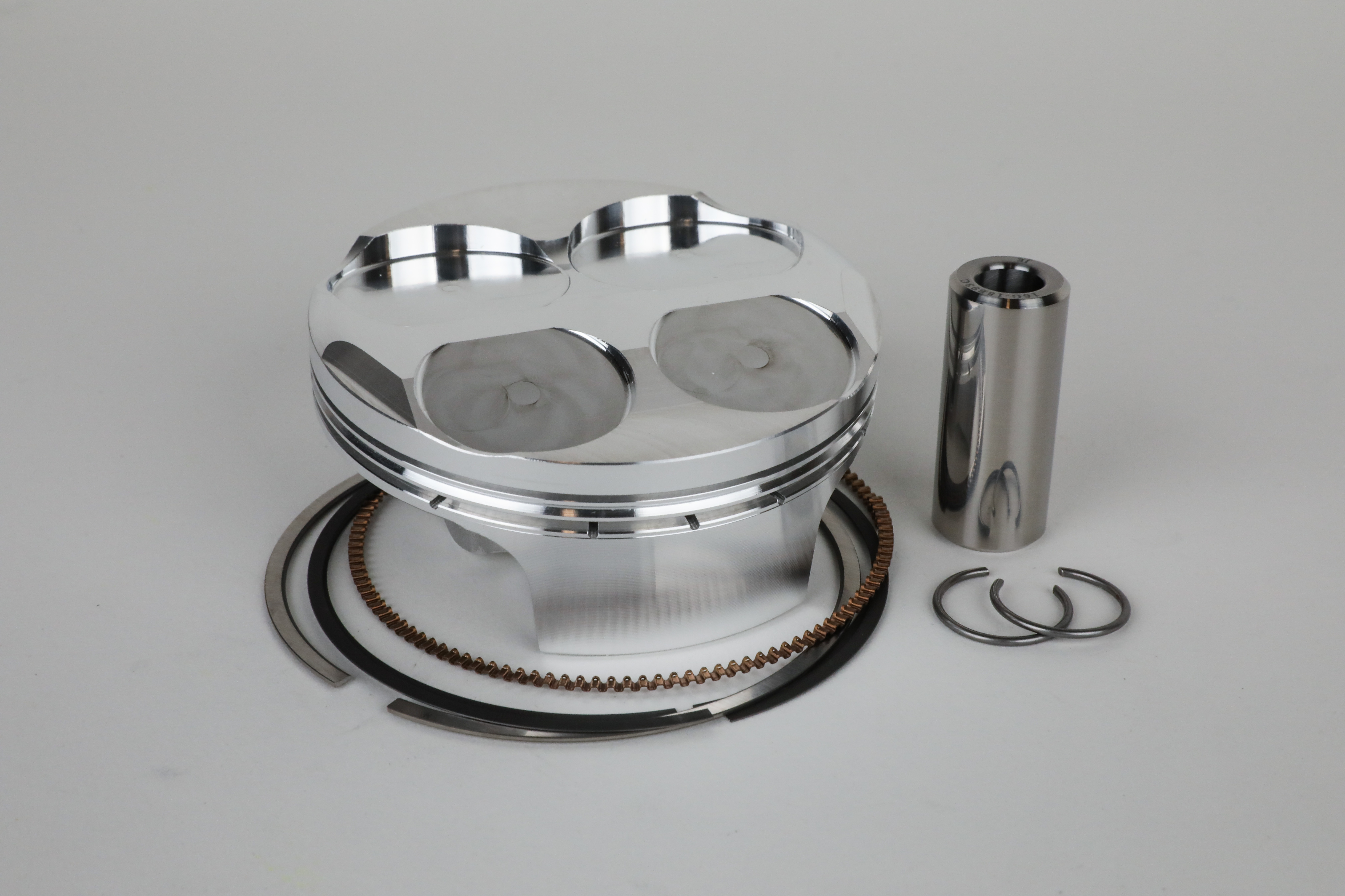
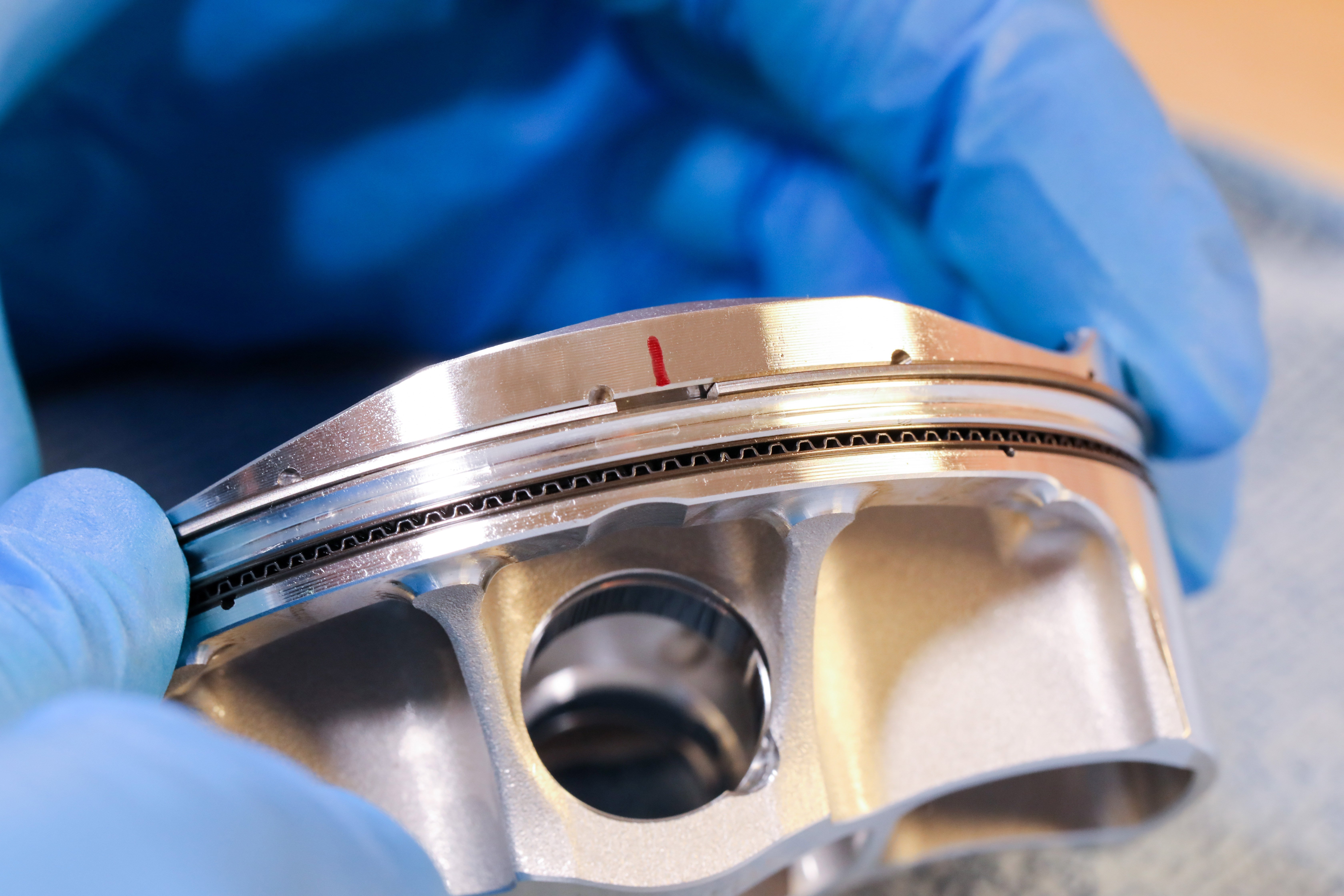
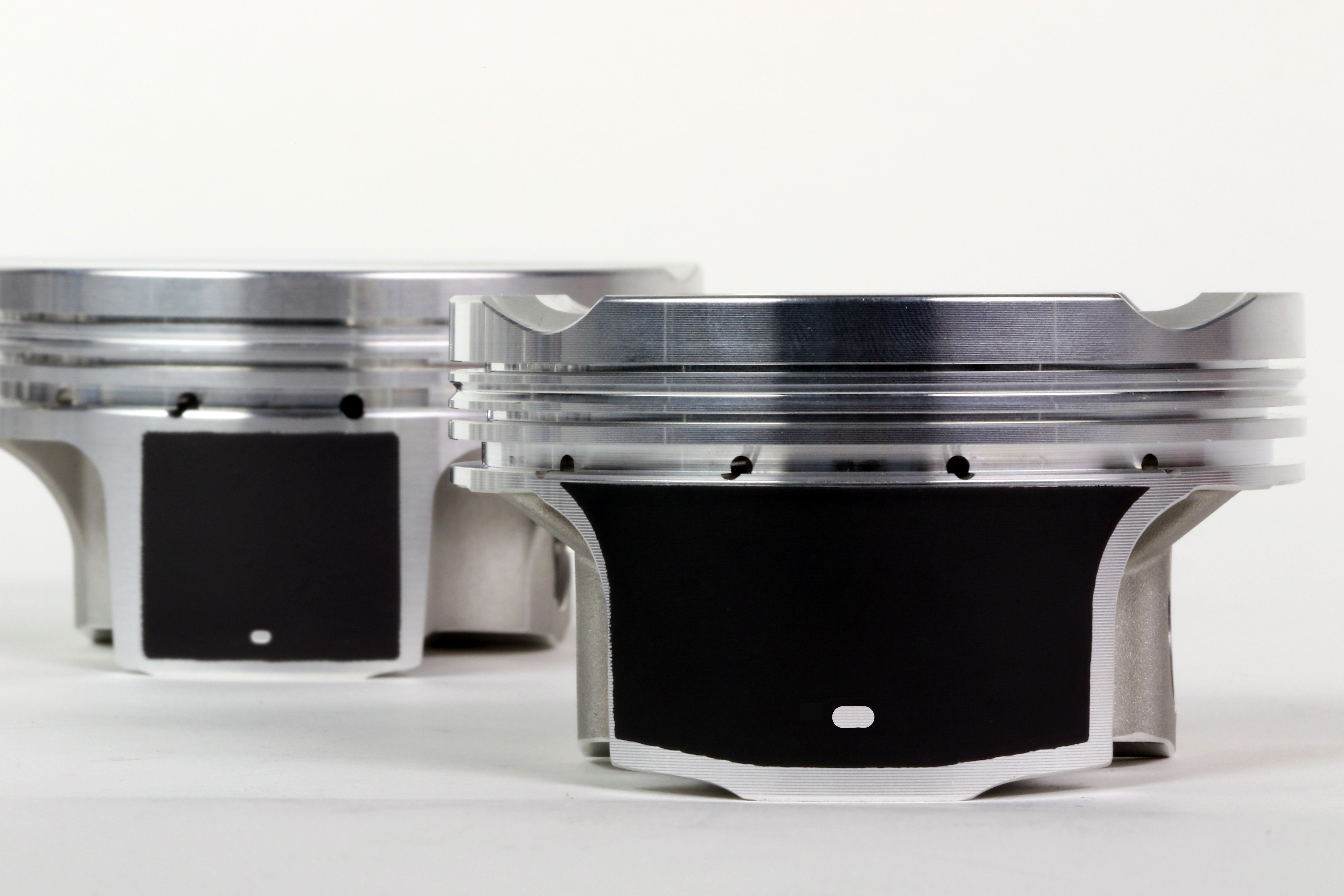
Need a piston? Find forged pistons for your bike here.
Before servicing your engine, you will need your machine’s factory service manual. The service manual is required because it specifies the required clearances, torque specs, and other information imperative to performing the task. The outline we’re providing should be considered supplemental to the information in your service manual and is in no way a comprehensive substitute.
To tackle this job, you’ll typically need the following tools and supplies:
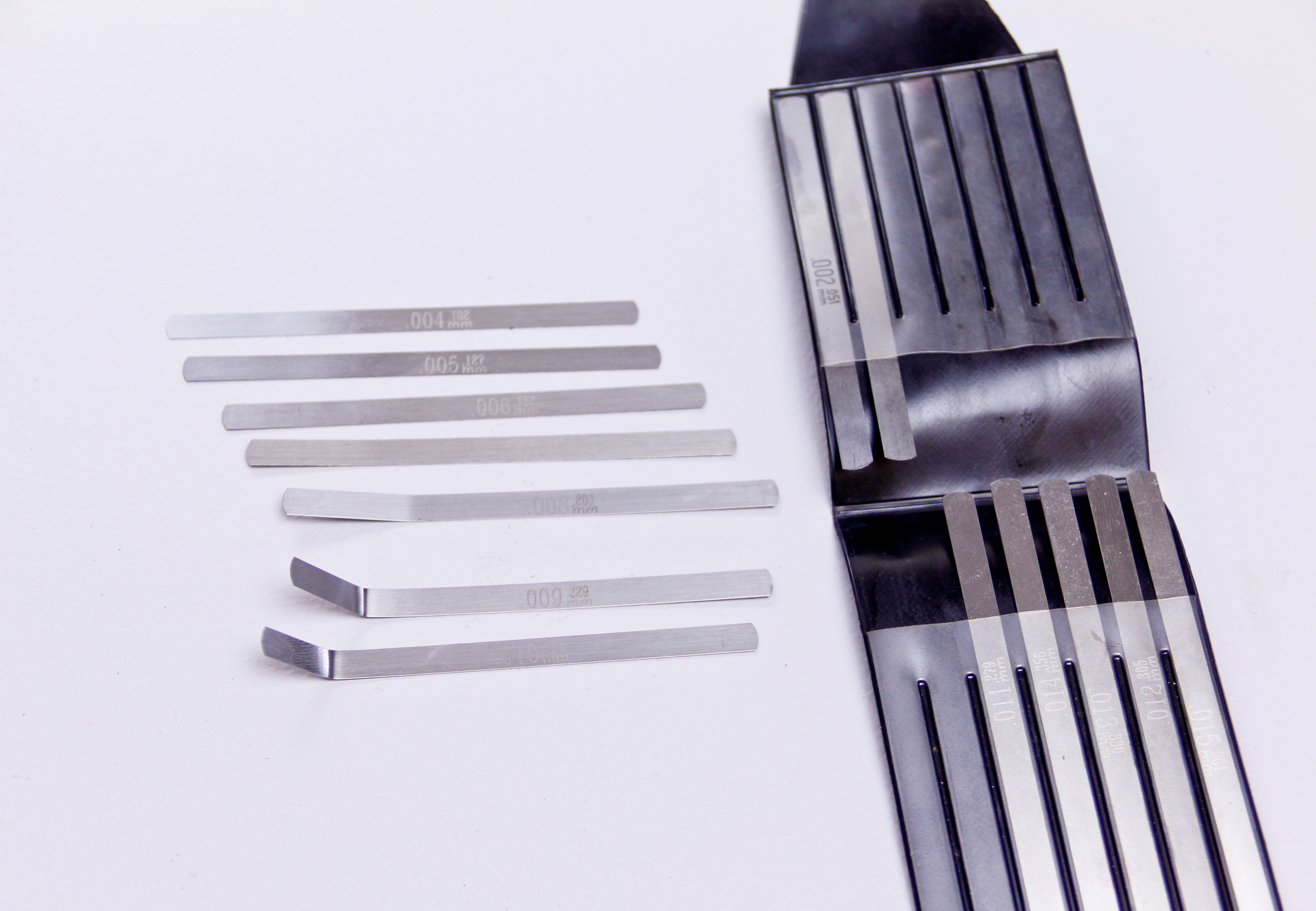
- Lash/feeler gauges
- Metric wrenches
- Metric sockets
- Clean rags or towels
- Screwdrivers
- Caliper
In most cases, specialty tools aren’t utilized, however, if they are, you’ll find that information in your service manual.
Since the engine is going to be partially opened up and exposed, it is best to work on a clean machine. If your machine is dirty, take the time to clean it thoroughly so the risk of contaminating the engine with debris is lessened. Prioritize cleaning the cylinder head cover and surrounding area.
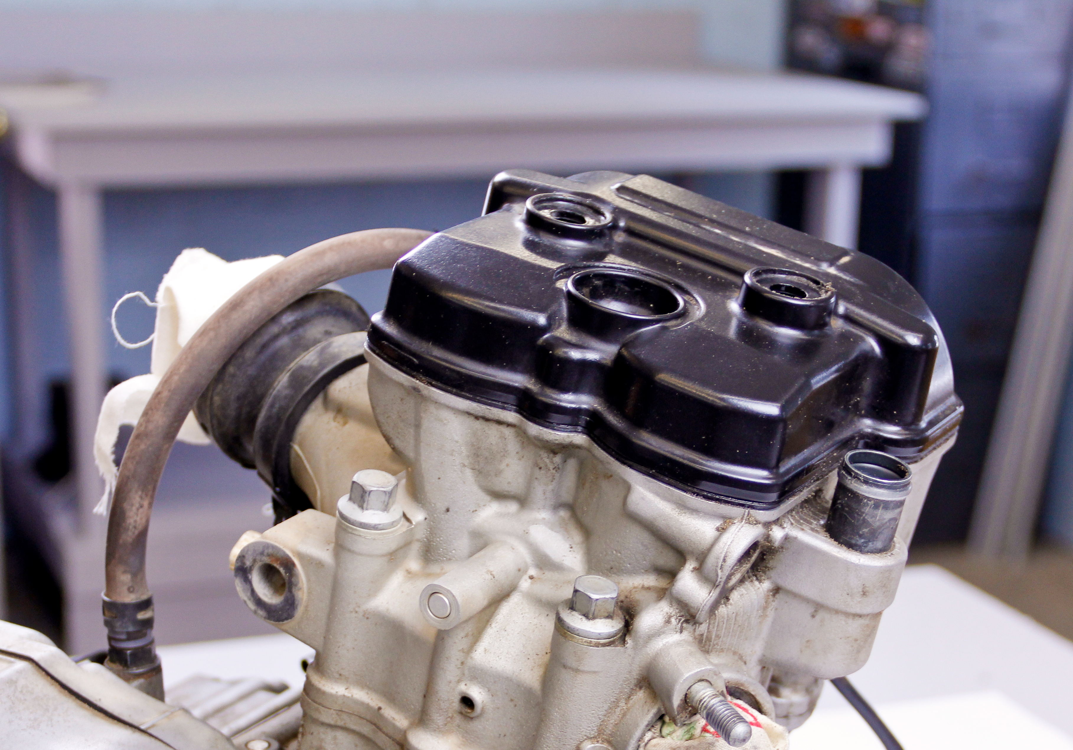
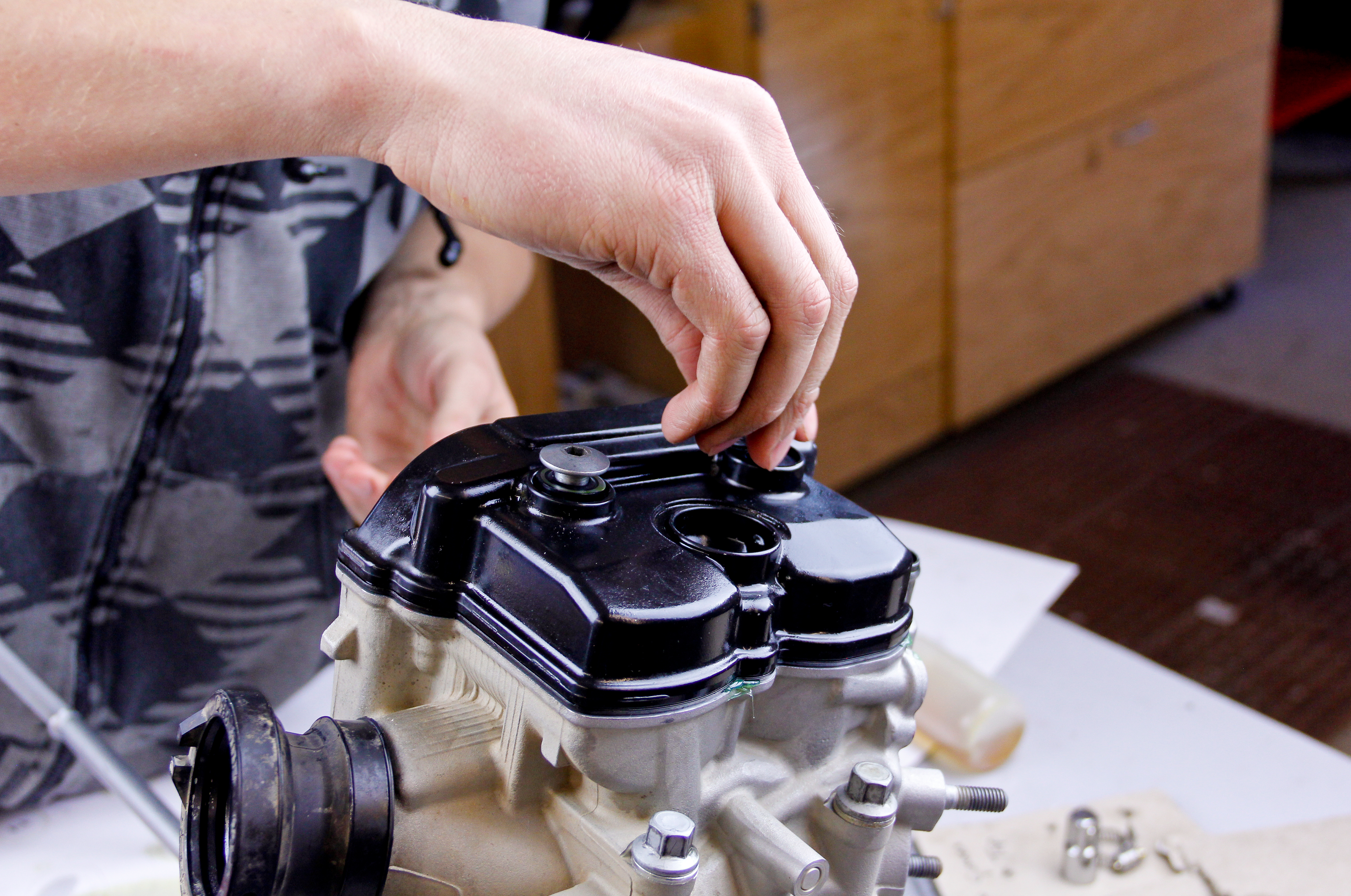
We’ll begin outlining the procedure with the removal of the cylinder head cover. You’ll likely need to remove your seat, fuel tank and various other components before this. These items should be easy to remove, and your service manual should provide sufficient guidance. When removing the cylinder head cover, be extremely careful not to allow dirt to fall into the cylinder head.
Next, the valvetrain will need to be positioned so that the clearances can be checked. Most service manuals specify setting the valvetrain so that the piston is at top dead center (TDC) on the compression stroke. Setting the valvetrain at this position ensures that the cam, or cams, are on their base circles and that neither the intake or exhaust valves are open. The base circle of the cam is the circular portion of the cam which does not influence valve lift.
As an aside and for future reference, while it is sensible to follow the service manuals recommendations on setting the piston position and engine stroke when the engine is assembled, it is not necessary, especially when working on an engine that is being rebuilt. Checking valve clearance can also be accomplished with the cylinder head removed from the engine and positioning the cam lobes opposite the lifter buckets to ensure the clearance measurements are taken with the cam on its base circle.
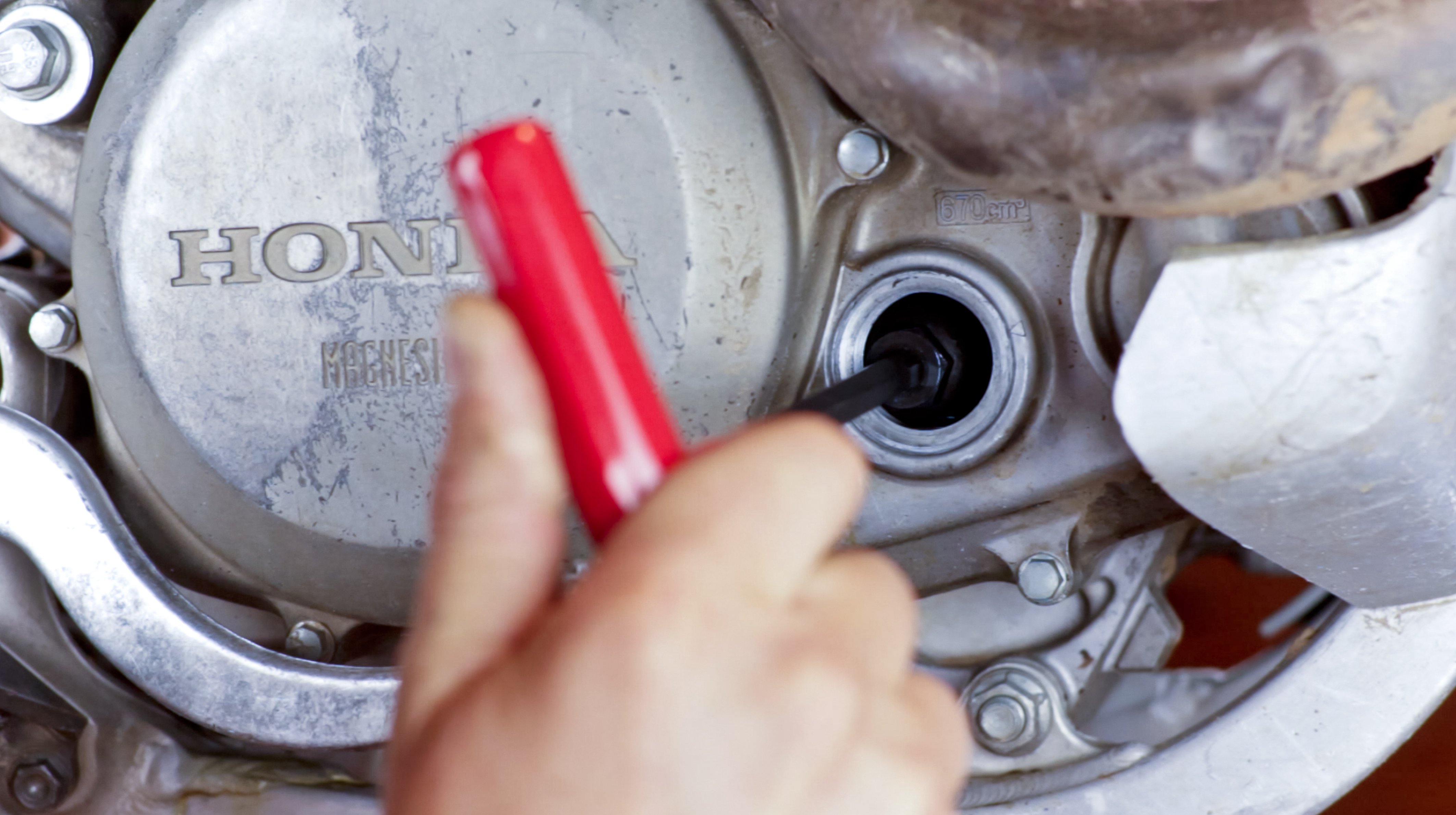
Your service manual outlines the required procedure to set the engine on its compression stroke at TDC. Most engines have mating alignment marks on the crankshaft and engine case as well as the cam gear and cylinder head. It is imperative that you know and understand how to utilize these reference points because they are used to correctly set the cam timing after any valve clearance adjustments have been made.
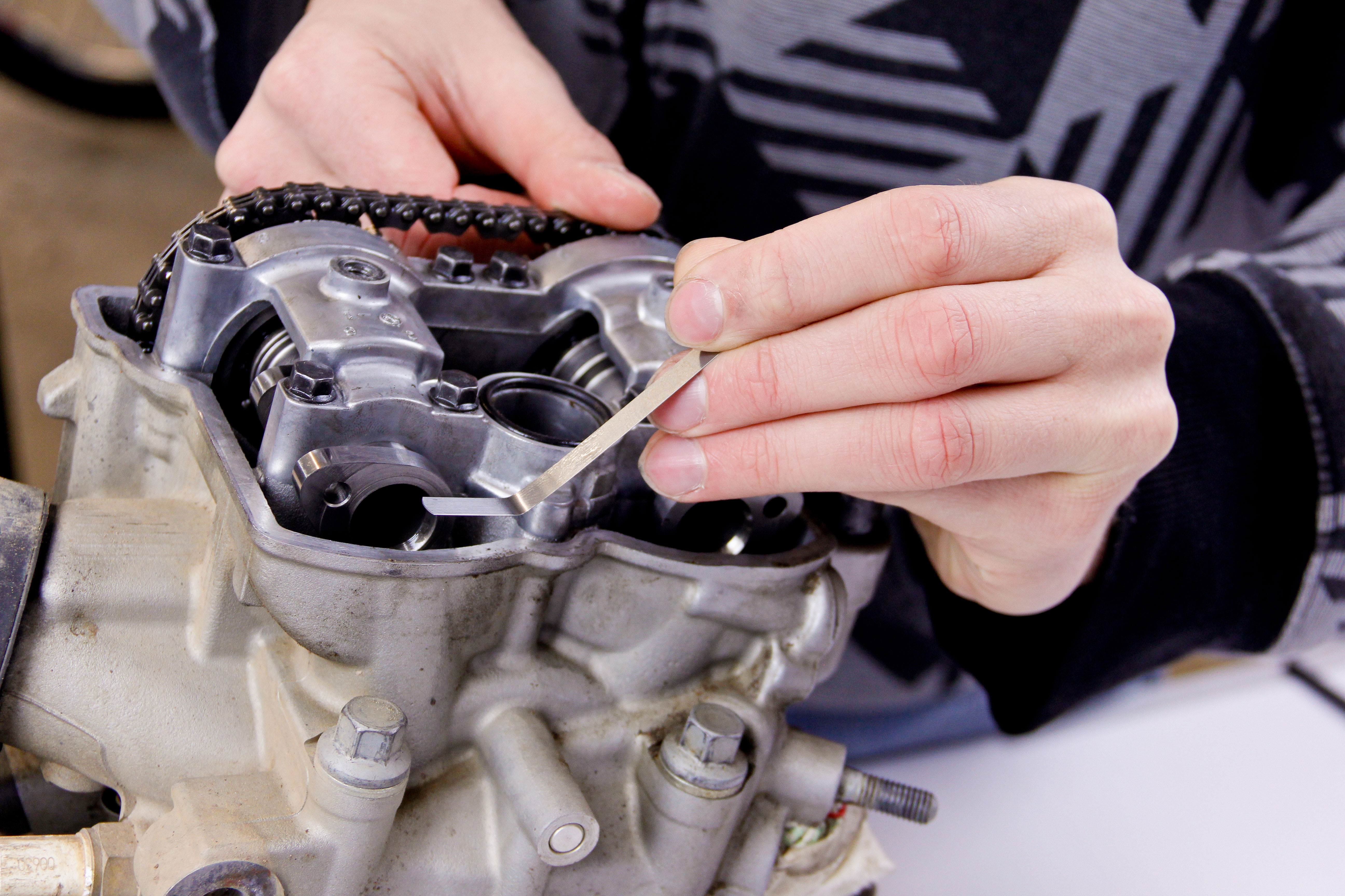
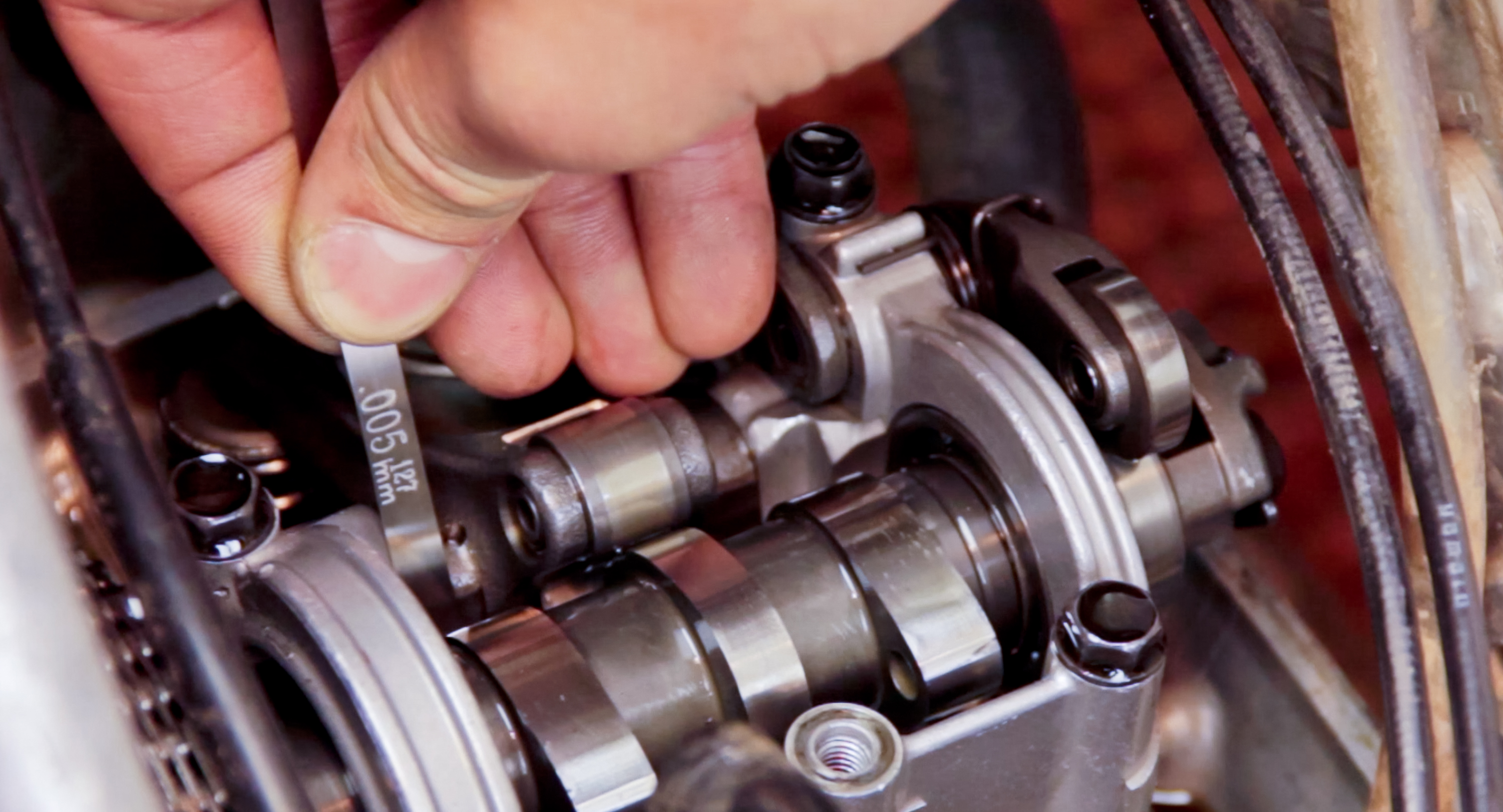
Once you’ve positioned the cams correctly, valve clearance measurements can be made using lash (feeler) gauges. Lash gauge measurements can be tricky due to surrounding geometry and inexperience on the user’s part. To obtain the most accurate measurement, it is essential that the lash gauge is inserted between the cam and lifter bucket as close to parallel as possible. To facilitate parallel entry, bend the lash gauges as necessary so that their tips can easily slide between the cam and lifter bucket.
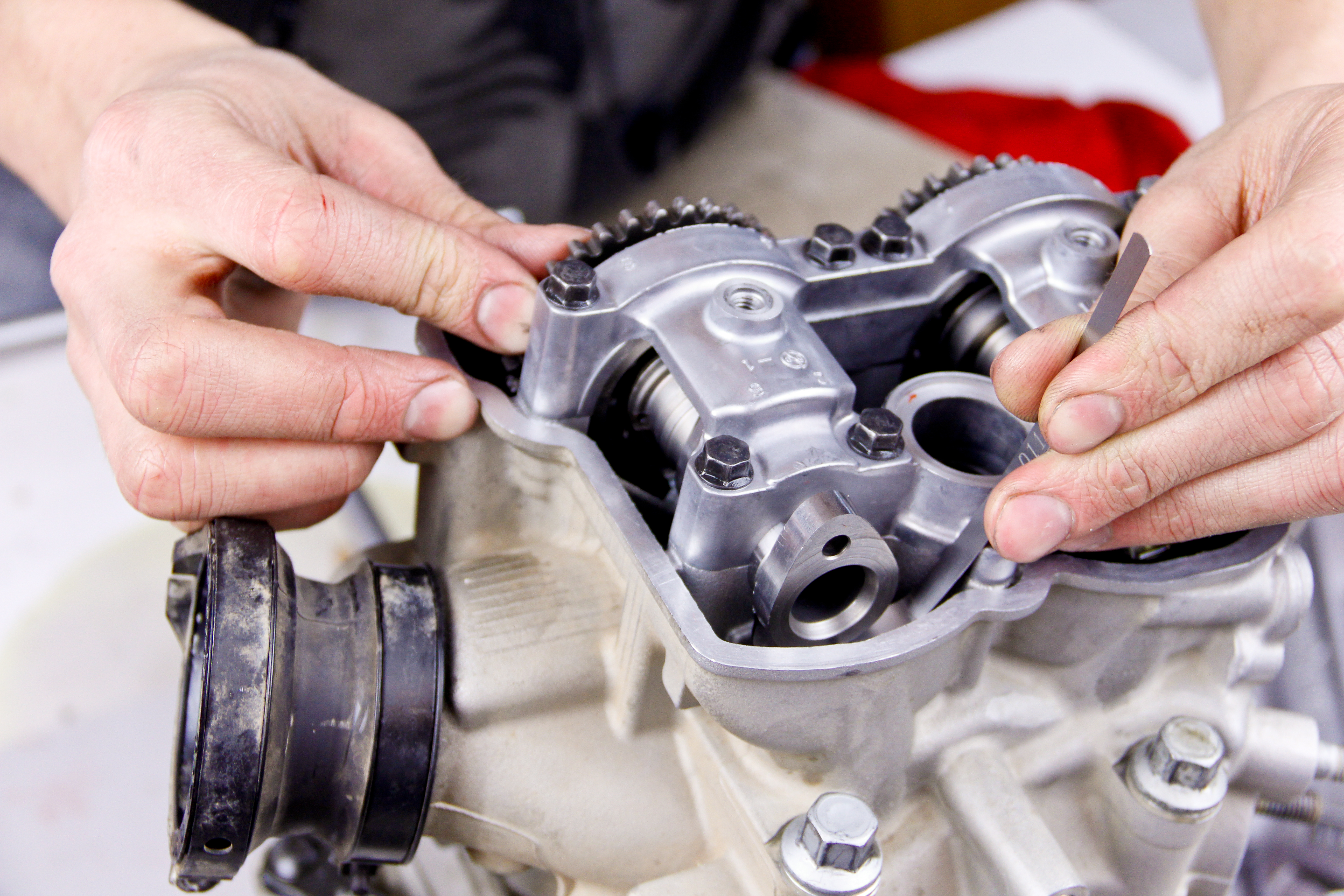
Accurate lash gauge measurements are subjective because they are based on feel. Ideally, the most accurate valve clearance measurements are obtained when the lash gauge passes between the cam and lifter bucket with a slight drag. Gauges that pass through easily or must be forced through should be considered too thin or too thick, respectively. When this occurs, other gauges should be tried, or, if you’re between sizes, the average of the two should be utilized as the valve clearance.
After each of the intake and exhaust valve clearances has been recorded, they should be compared to the service specifications outlined in your service manual. If the valve clearances fall within the manufacturer’s recommended range, no further work is required. However, if the clearances are outside of the specifications, determining what adjustments need to be made is the next step. To do this, unless the current valve shim thicknesses are known, the cylinder head will have to be disassembled so that the shims can be removed and measured.
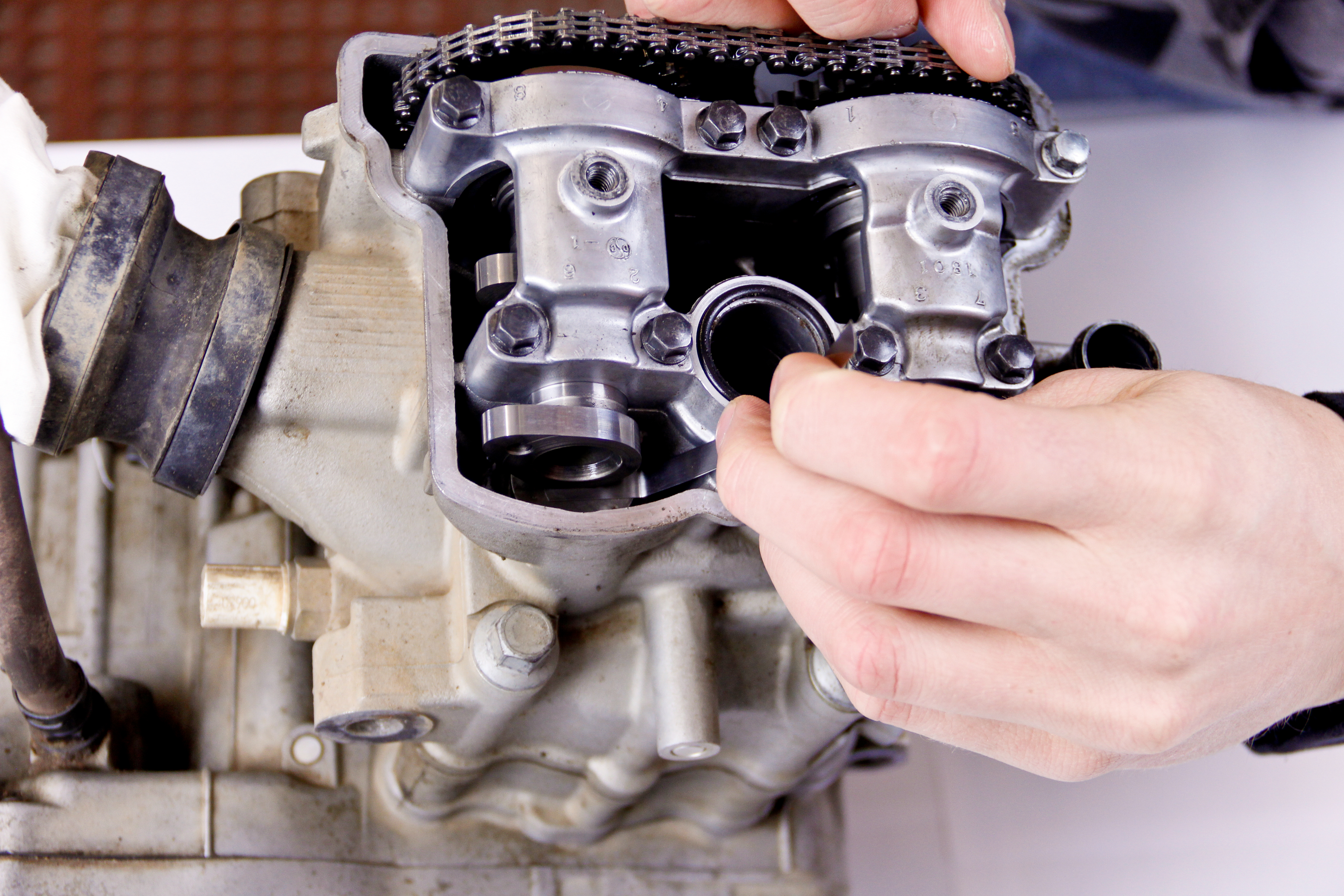
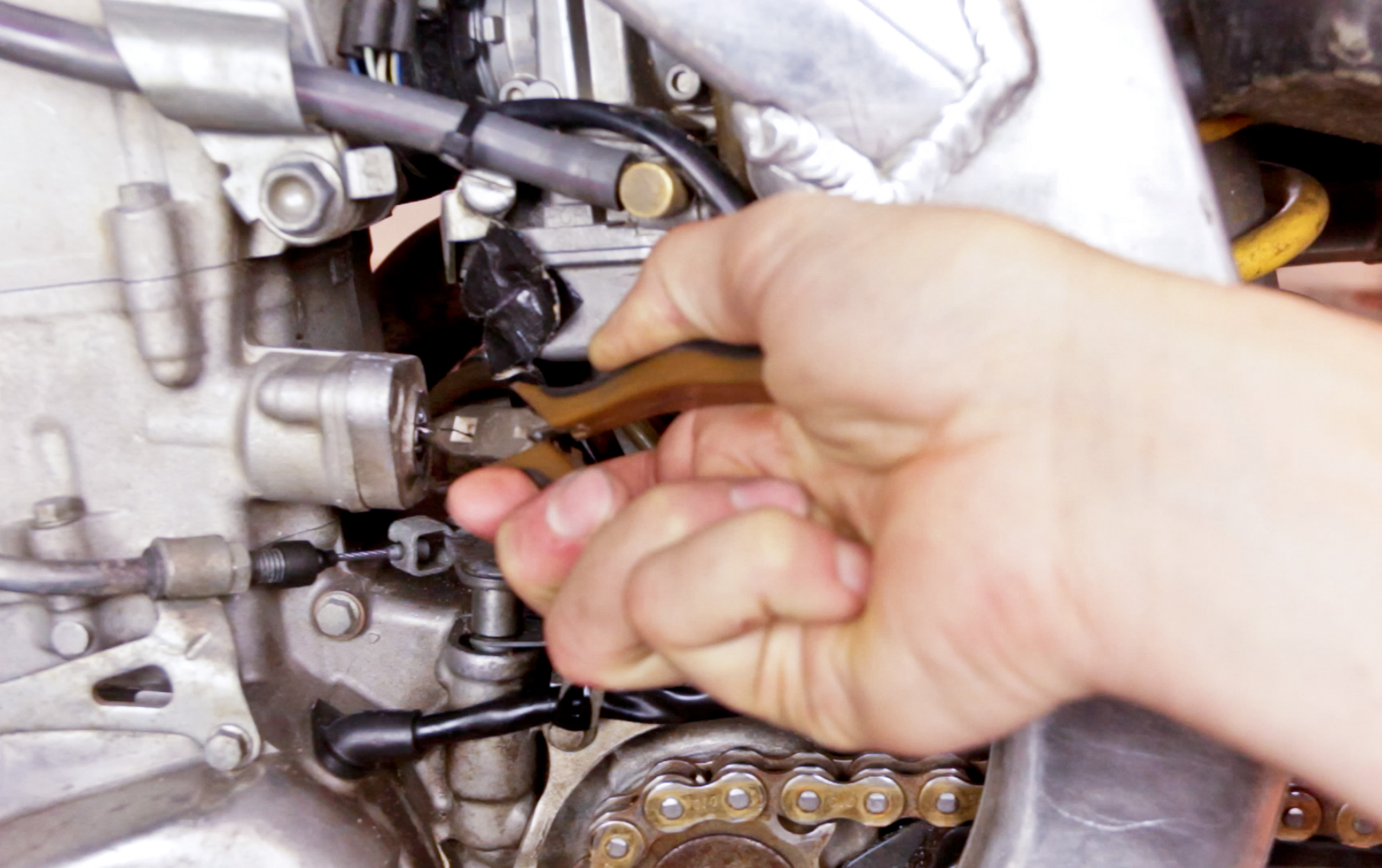
Follow the necessary procedures outlined in your service manual to slacken the cam chain, remove the cam cap, cams, and lifter buckets. When removing the cam cap, be sure to follow any recommended removal/tensioning sequences. Once the cam chain is free, use a piece of wire to secure it to the cylinder head. If it happens to fall in the chaincase, a pen magnet can be used to fish it out.
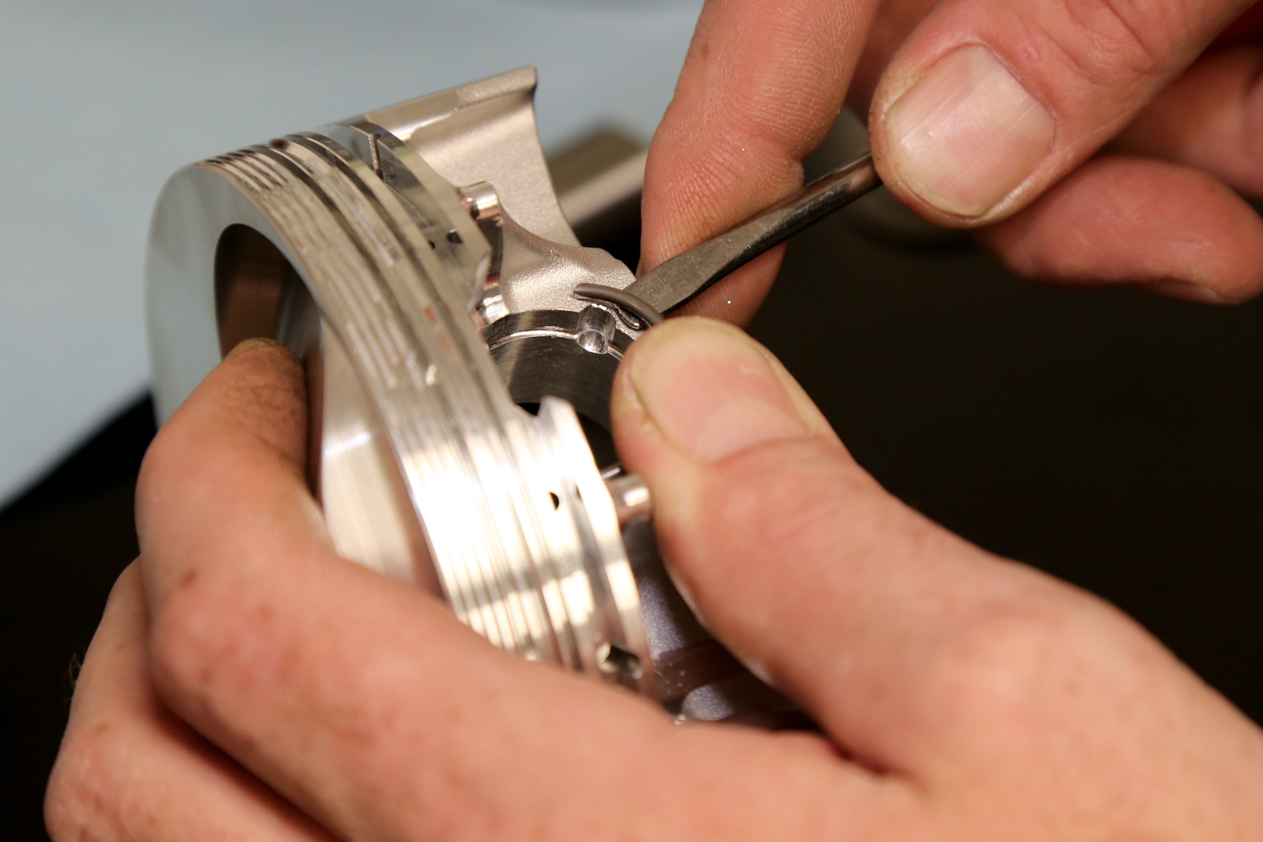
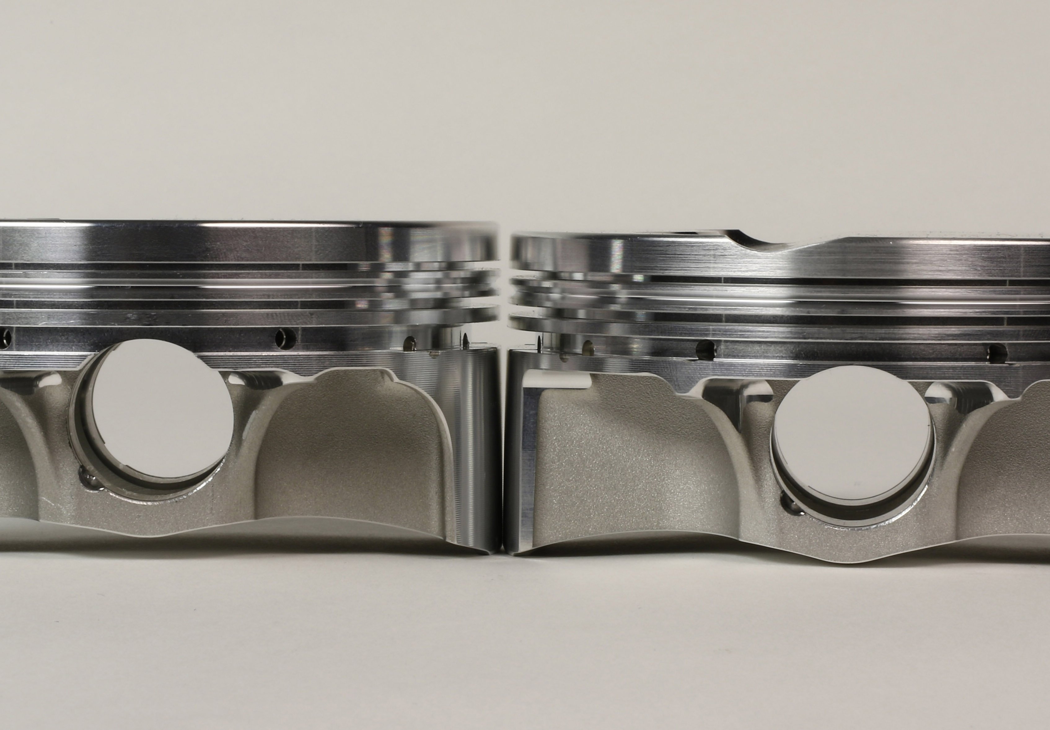
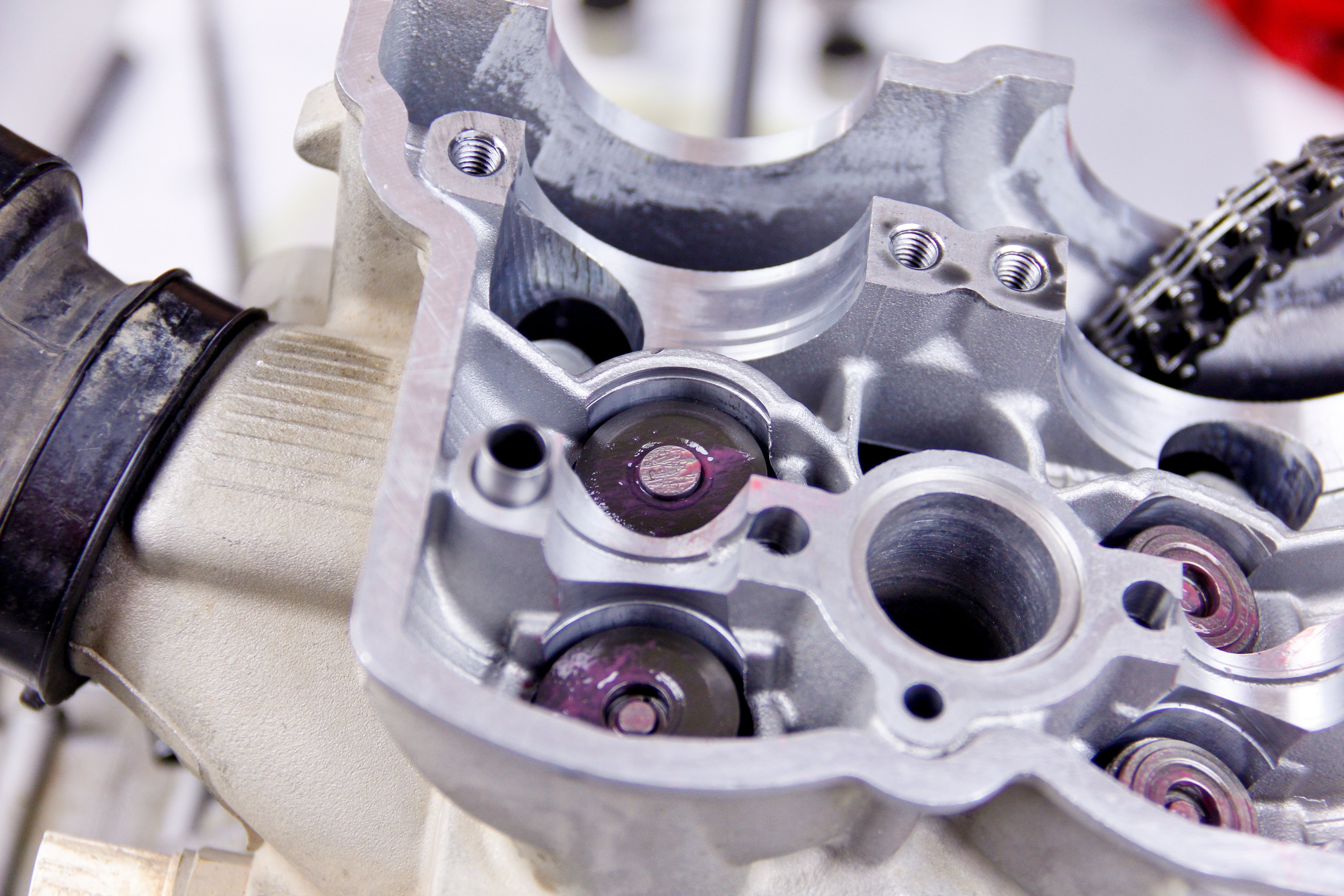
To remove the lifter buckets, a pen magnet or valve lapping tool are both excellent aids to utilize. When extracting the lifter buckets from their bores, be very careful and keep tabs on whether or not the valve shim sticks to the underside of the bucket. Oil underneath the lifter buckets makes sticking shims a common occurrence.

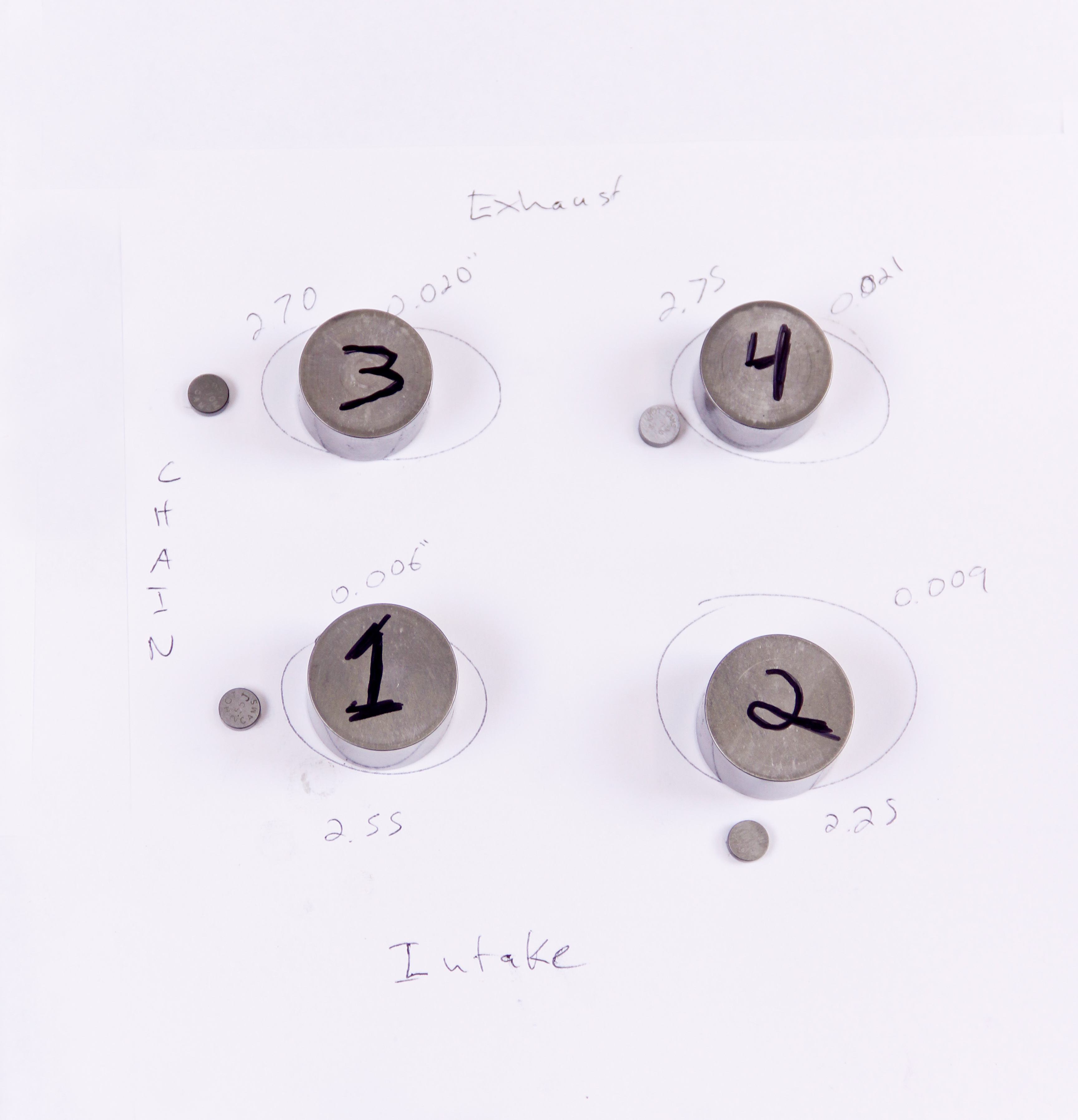
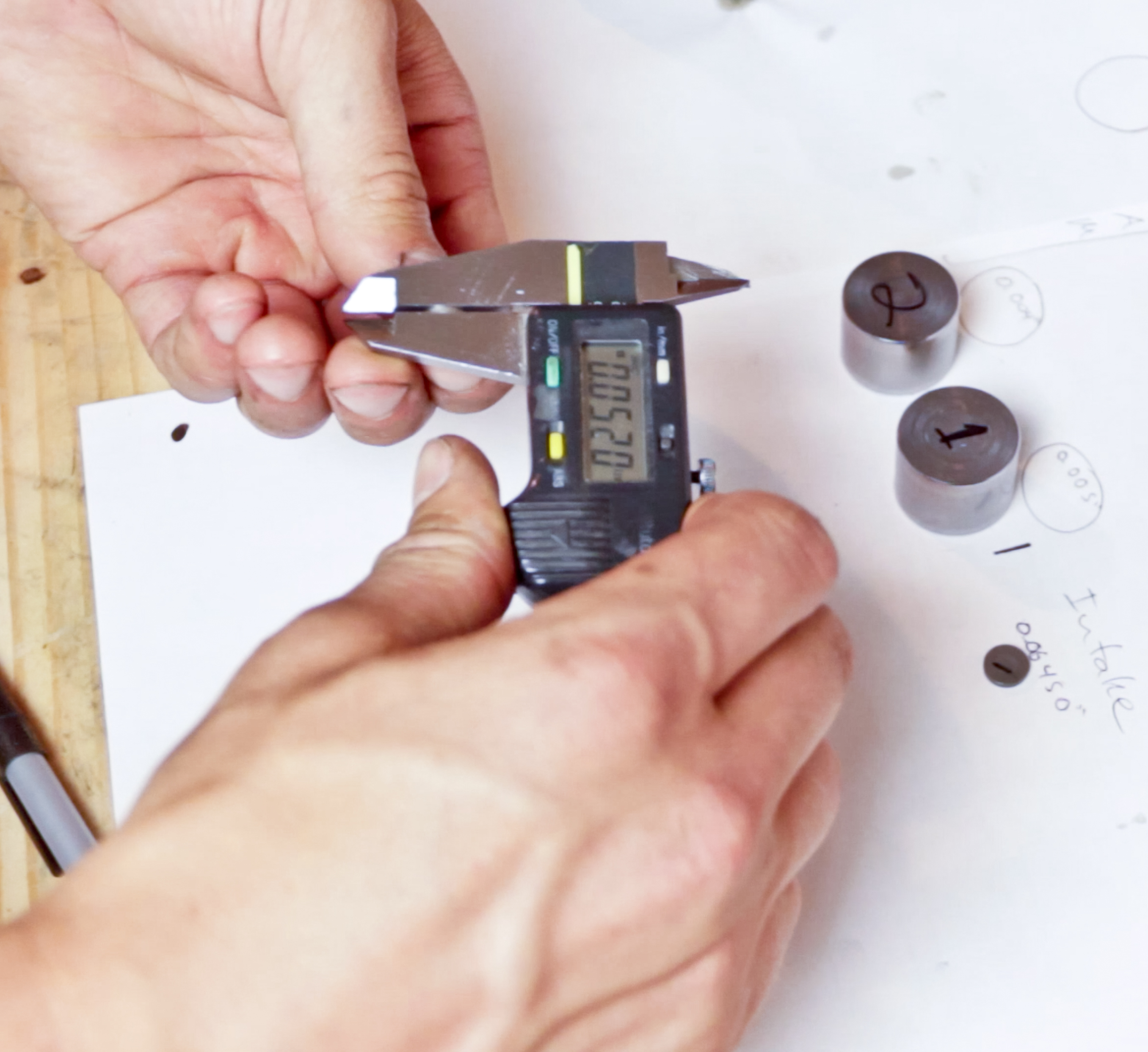
Through engine operation, the lifter buckets mate to their respective bores so they should never be mixed around. To help keep track of things, draw out a simple cylinder head diagram on a piece of paper so that the lifter buckets and all the measurements can be tracked. Proceed to remove any remaining valve shims from the cylinder head. Once the valve shims have been removed, measure the shim thicknesses and the diameter of shims used.
To determine what valve shim adjustments should be made, a simple formula is used:
New Shim Thickness = Recorded Clearance - Specified Clearance + Old Shim Thickness
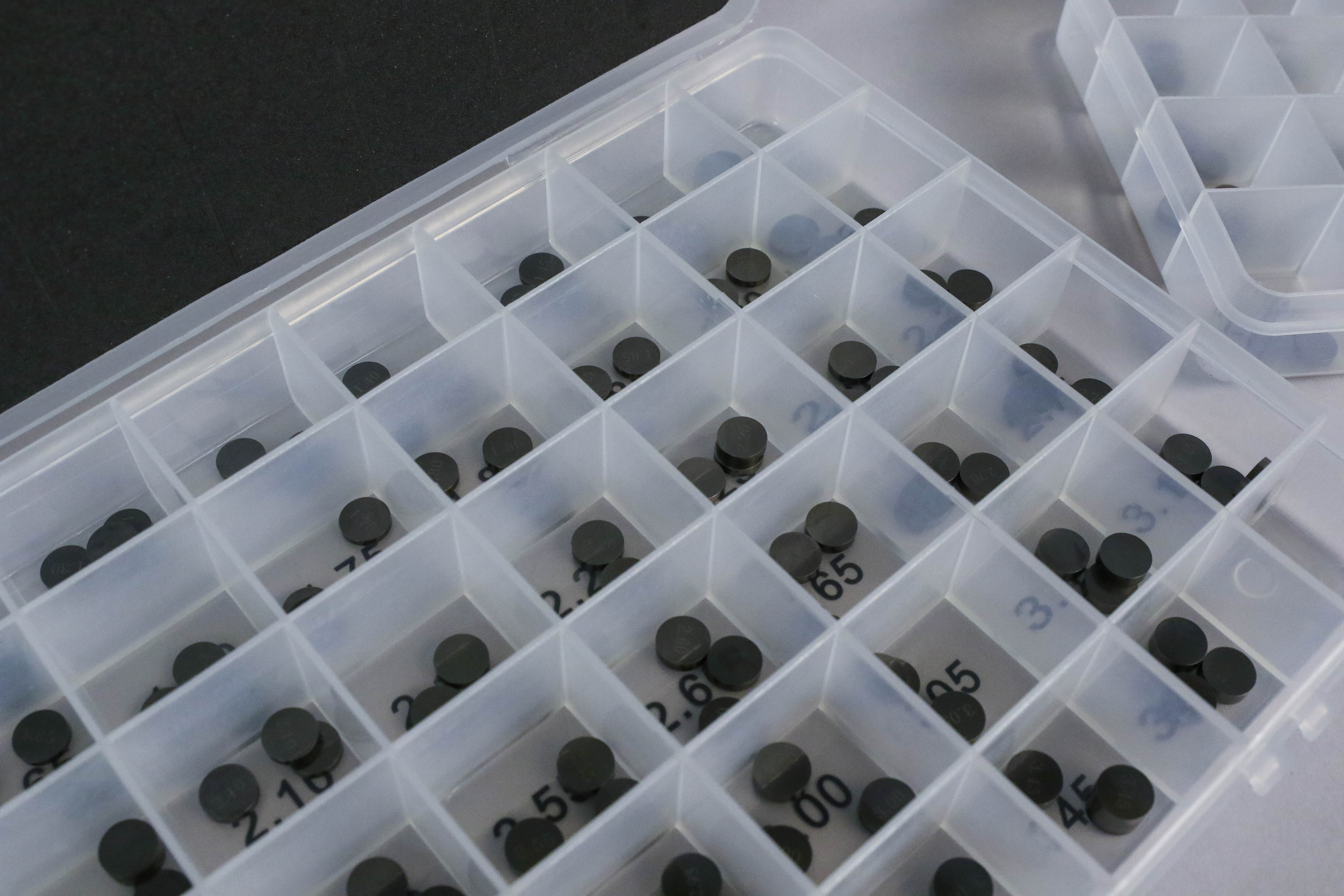
Calculate the necessary new shim thicknesses for all the clearances that are out of spec. Valve shims are available from most OEMs, but helpful shim kits that come with an assortment of sizes are also available from the aftermarket. Before sourcing shims, you’ll need to determine the diameter of the shim you need because there are a handful of different shim diameters used within the industry. Shown below are the standard shim diameters.
|
Size (mm) |
Manufacturer |
|
7.48 |
Japanese |
|
9.48 |
Japanese |
|
8.90 |
KTM |
|
10.00 |
KTM |
When calculating what new shim thicknesses are required, it is best to target the specified clearance on the upper end of the prescribed clearance range. This is advised because valve clearances usually diminish over time. Valve shims are available in 0.025mm increments, so the shims that can be utilized will also influence the new clearances that can be achieved.
Once you have the correct shims in hand, the valvetrain can be reassembled. Use engine oil to lubricate the valve shims and carefully install them. The lifter buckets should also be lubed before installation. When inserting the lifter buckets into their respective bores, ensure that the buckets bottom on the shims and at no point comes back up. If the bucket comes back up upon installation, occasionally the shim will stick to it and become displaced. The engine can quickly be severely damaged if the shim is not seated correctly between the valve stem and lifter bucket.
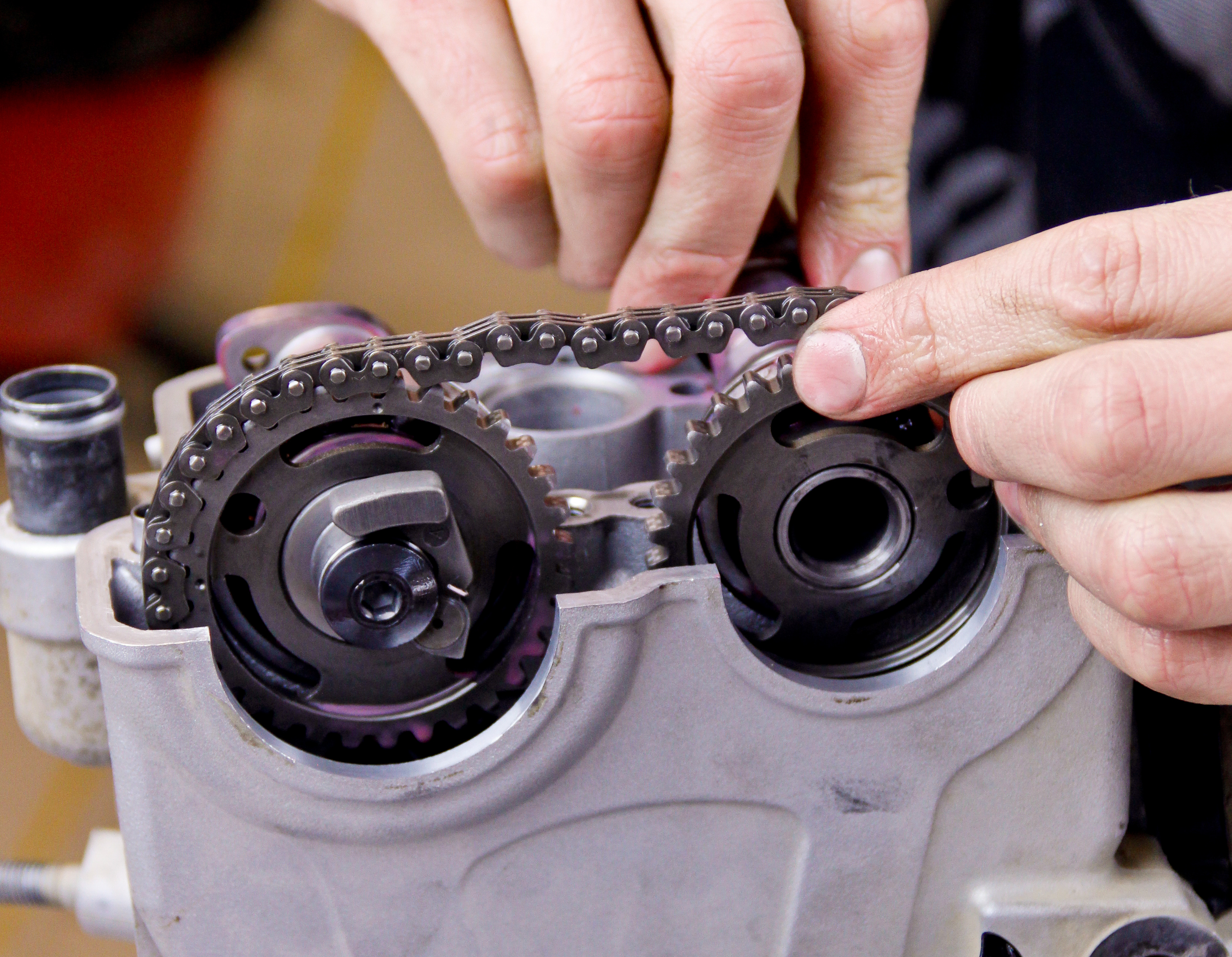
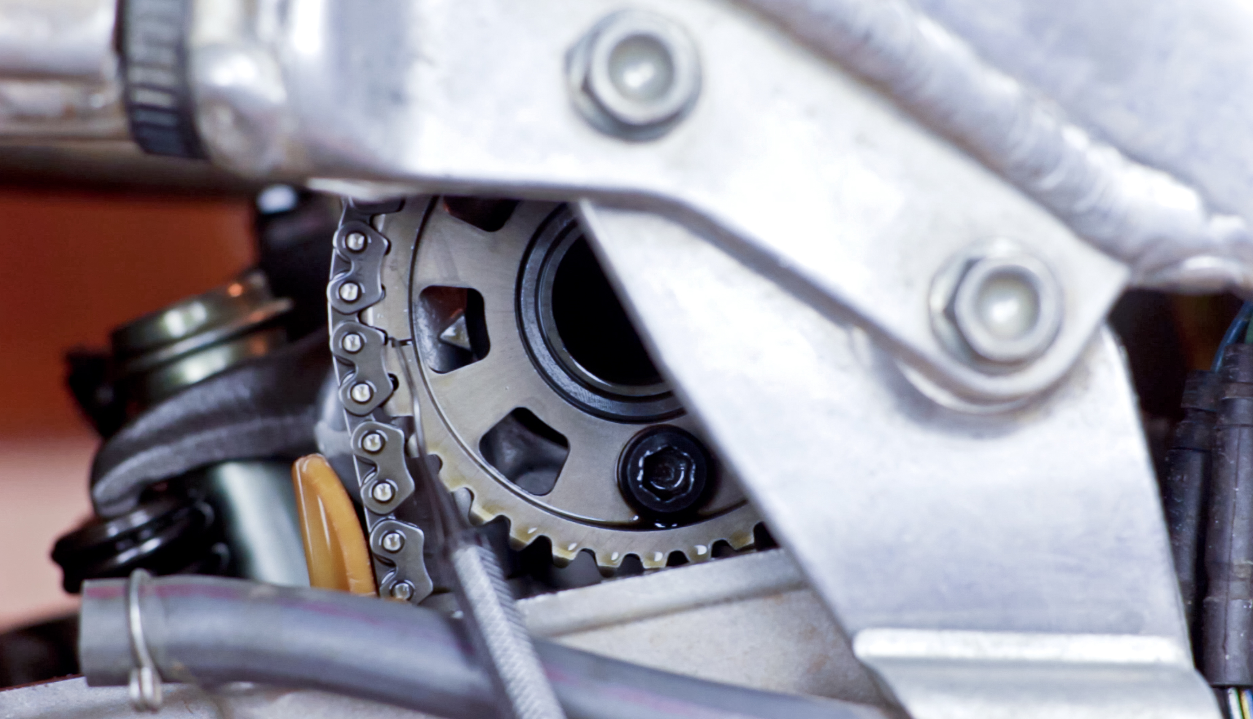
Pay close attention to your service manual during installation of the cams and when setting cam timing. Double check that the crankshaft is in its correct position. If you’re working on a twin cam engine, it is best to install the camshaft that resides opposite of the chain tensioner first (typically the exhaust cam), pull the chain taught from the crankshaft, orient the cam gear correctly, and then wrap the chain around the gear. Once this is accomplished, the remaining cam can be oriented correctly and the chain wrapped around it. Double check orientation of all components and that timing has been set correctly. Be sure to use engine oil to lube the cam bearing bores upon installation.
Click here for a more in-depth guide to setting cam timing.
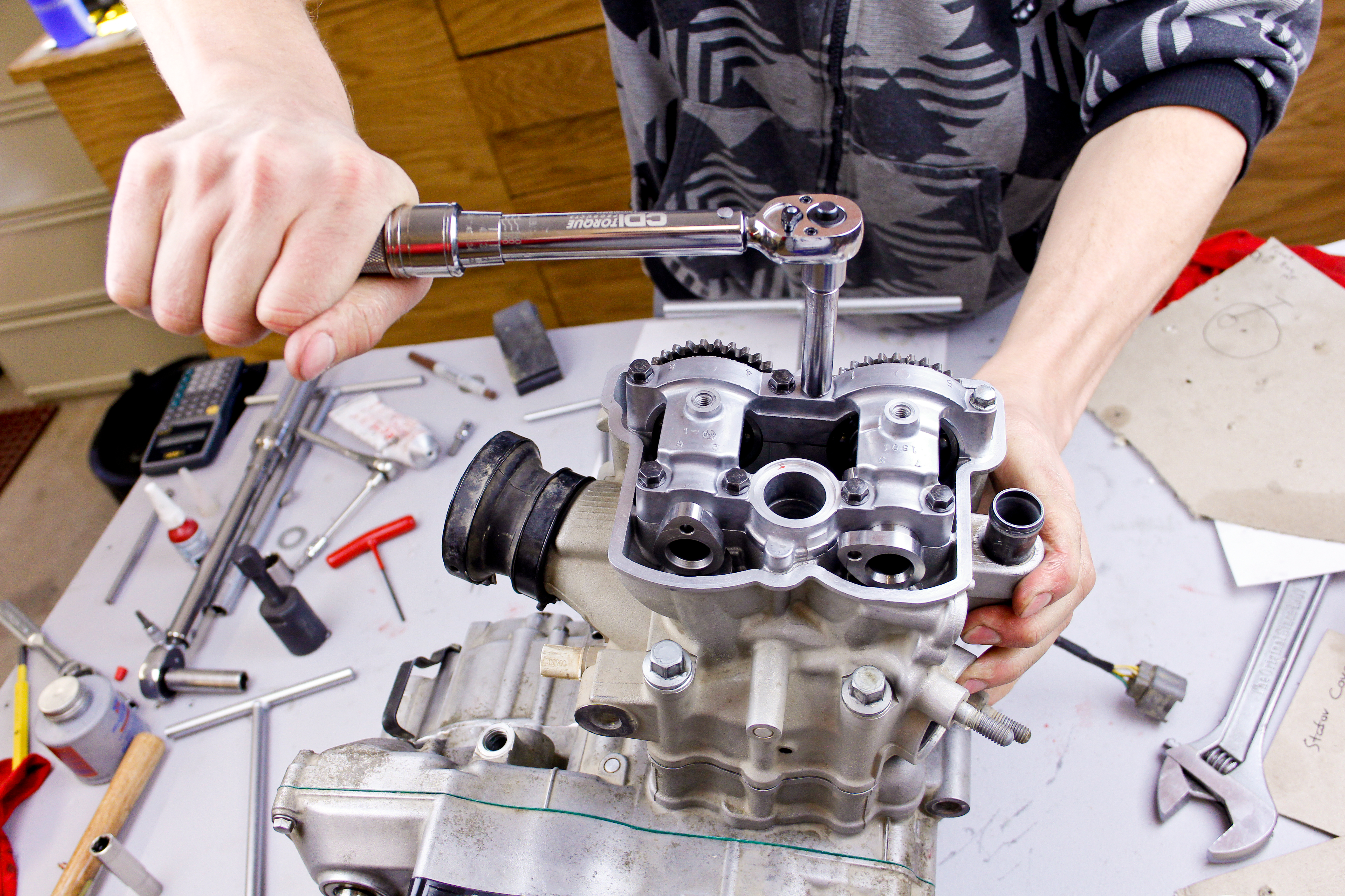
When installing the cam cap, ensure the torque specs and sequences outlined in your service manual are followed. Deviations from either can cause the cam bearings to wear prematurely. Once the cams have been secured, use lash gauges to confirm the new valve clearances match the clearances that were calculated. Any deviations that are found should be carefully scrutinized because they may be indicative of calculation errors or shims that are not seated correctly. If there is a hint of a problem at this point, it is imperative that it is thoroughly understood and corrected before proceeding.
Assuming everything checks out, the cam chain can be tensioned. Follow the procedure outlined in your service manual to do so. Once the tension has been set, rotate the engine through at least four complete revolutions. Doing so will help the automatic chain tensioners to set the correct initial tension and confirm that the engine has been timed correctly. Position the piston at TDC on the compression stroke and check that all timing features on the crank and cams remain in their specified positions.
Complete the job by carefully reinstalling the cylinder head cover, making sure to torque those bolts in a star sequence to recommended specs. Once the rest of the machine is buttoned up, it’s time to get back to riding!
Images provided and owned by Kelsey Jorissen Photography, LLC.